FSN Series • User’s Guide • Rev 01 113
4. Installation
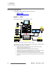
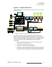
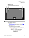
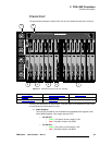
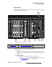
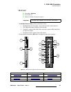
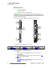
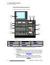
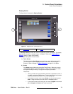
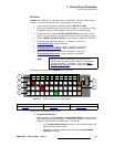
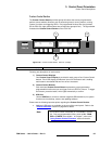
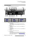
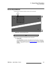
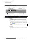
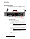
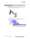
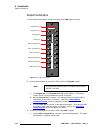
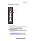
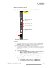
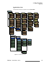
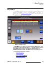
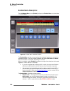
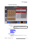
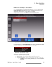
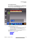
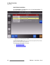
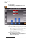
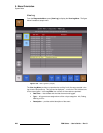
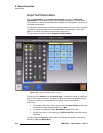
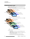
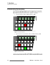
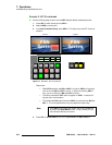
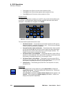
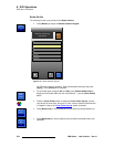
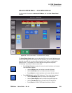
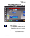
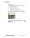
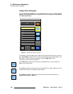
FSN-1400 System Connections
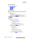
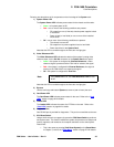
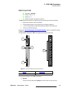
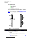
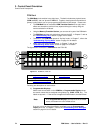
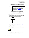
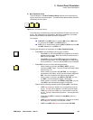
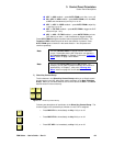
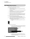
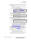
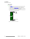
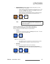
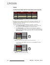
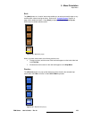
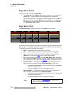
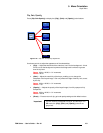
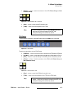
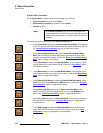
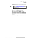
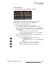
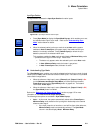
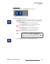
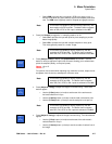
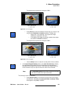
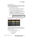
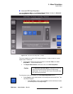
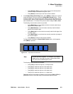
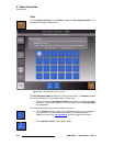
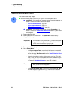
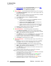
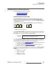
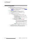
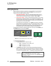
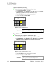
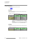
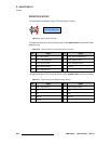
3. (Recommended) Using a BNC cable, connect an analog reference video input to
the Ref In connector. This connection enables you to genlock the FSN Series to
an external reference.
~ Accepted signals are black burst, SMPTE bi-level sync and tri-level sync.
~ Computer sync is not an accepted signal.
~ If you do not elect to connect reference video, you can set the system to
“free run” on the Reference and Output Setup Menu.
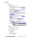
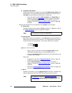
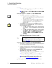
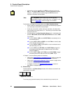
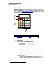
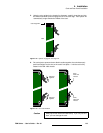
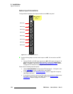
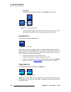
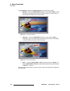
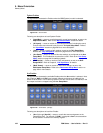
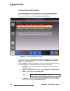
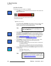
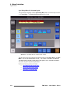
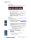
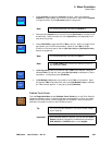
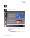
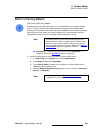
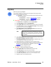
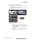
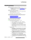
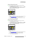
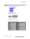
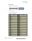
4. (Optional) Using a BNC cable, connect the Loop connector to the reference
video input on the next device in your video system. This connection enables you
to “daisy-chain” reference video to additional devices.
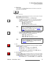
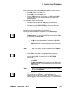
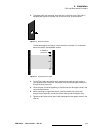
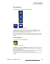
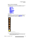
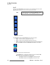
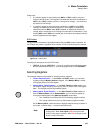
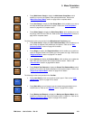
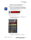
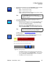
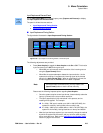
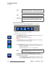
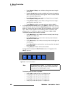
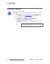
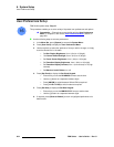
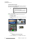
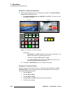
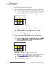
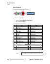
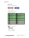
5. (Optional) Using a BNC cable, connect the Ref Out connector to the reference
video input connector on the next video device in your system, or to a reference
DA (distribution amplifier) for multiple reference feeds.
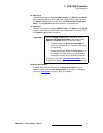
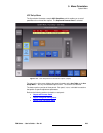
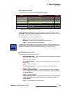
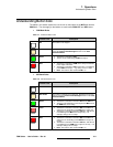
Please note:
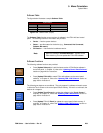
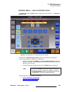
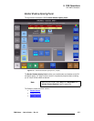
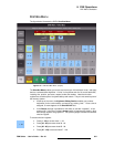
~ Using the {Reference Out} button on the Reference and Output Setup
Menu, toggle this output between Tri-Level Sync and Black Burst.
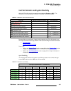
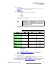
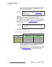
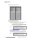
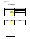
~ The sync out format (as provided on the connector) changes, depending
on the selected native video format. In Appendix A, refer to the
“Reference Video Output Specifications
” section on page 434.
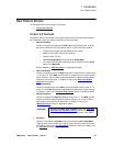
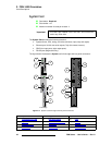
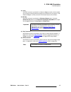
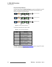
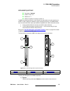
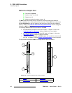
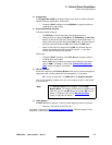
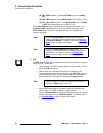
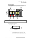
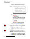
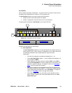
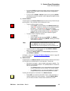
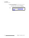
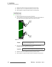
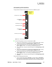
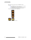
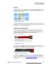
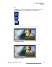
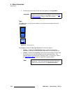
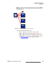
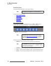
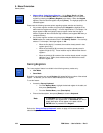
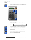
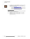
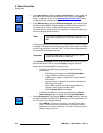
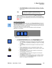
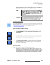
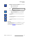
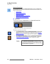
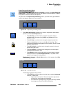
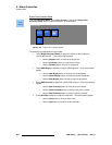
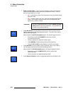
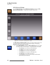
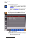
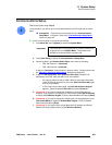
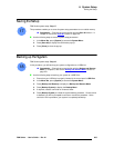
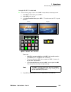
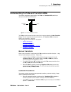
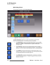
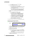
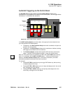
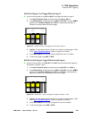
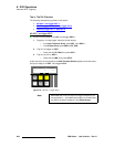
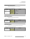
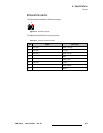
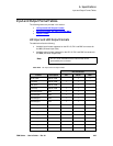
6. (Optional) Connect the supplied Tally “Y” Adapter to the Tally connector. This
adapter splits the DB-50 connector into two DB-25 female connectors, to simplify
your tally connections. Next, connect the tally relays to your video devices as
required. In Appendix A, see the “Tally Connector
” section for pinouts.
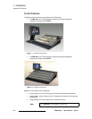
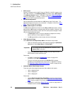
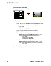
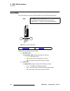
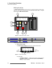
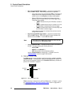
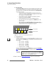
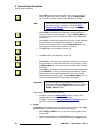
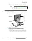
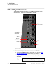
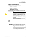
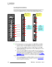
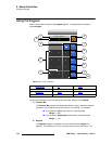
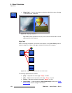
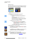
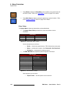
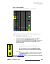
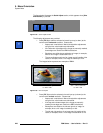
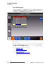
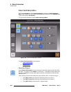
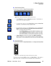
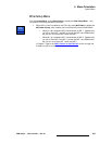
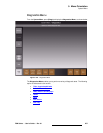
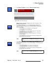
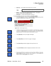
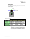
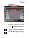
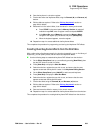
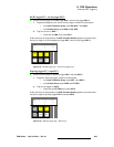
7. For AC connections, one AC connector is provided for each FSN-1400 power
supply. Please note:
~ One supply is standard, the redundant supply is optional.
~ In a redundant configuration with both supplies installed, the FSN-1400
can be powered from two different circuit breakers.
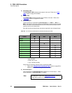
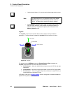
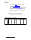
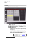
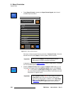
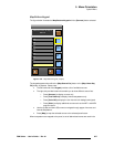
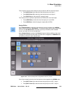
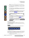
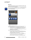
Open the FSN-1400 front door and note the number of power supplies installed. If
only one supply is installed, note its location (in the top or bottom slot).
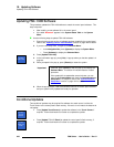
Note
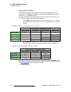
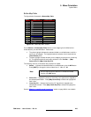
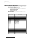
In Appendix A, refer to the “Reference Video Input
Specifications” section on page 433 for detailed information
about the allowed frame rates for the reference input.
Important
If the reference Loop connection is not used, connect a 75
ohm terminator to the connector.
Important
This connection assumes that the FSN-1400 is the “master”
sync source in your system, for distributing an advanced sync
signal to additional devices such as cameras.