204 FSN Series • User’s Guide • Rev 01
5. Menu Orientation
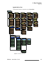
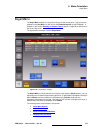
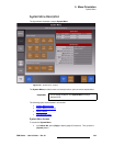
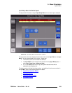
System Menu
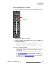
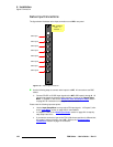
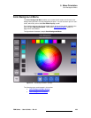
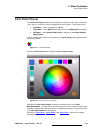
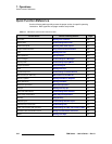
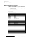
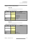
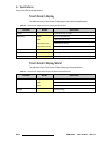
`çååÉÅíçê=`çäçêë
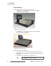
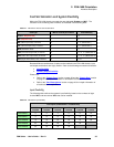
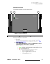
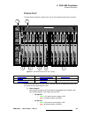
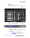
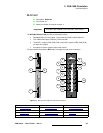
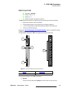
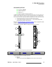
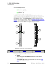
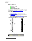
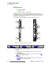
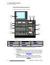
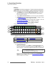
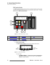
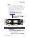
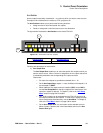
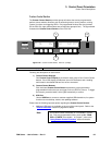
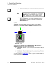
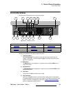
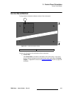
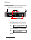
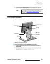
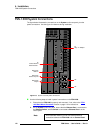
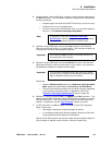
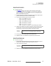
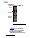
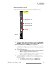
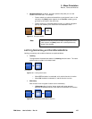
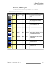
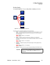
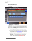
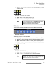
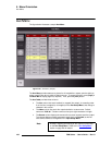
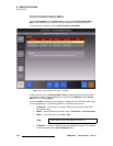
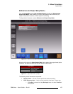
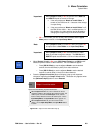
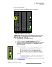
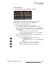
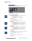
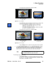
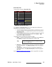
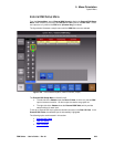
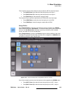
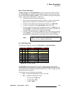
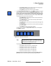
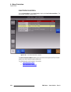
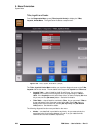
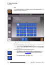
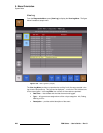
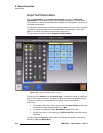
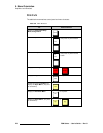
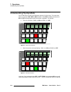
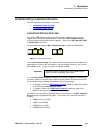
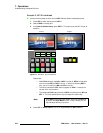
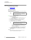
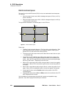
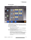
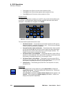
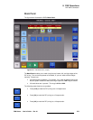
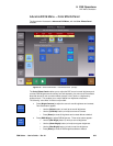
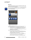
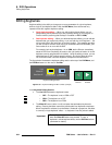
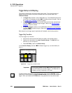
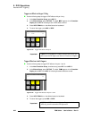
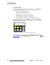
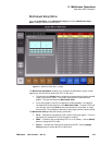
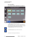
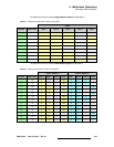
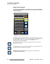
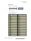
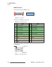
On the Rear I/O Views of the UIC, NIC and M/E panels, the color of the individual input
connectors is significant:
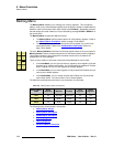
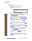
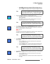
• Green indicates that the input is mapped to the control panel, and the signal is
OK.
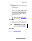
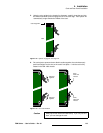
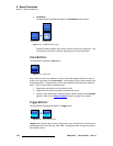
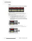
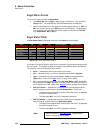
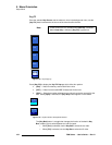
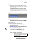
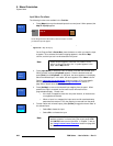
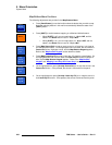
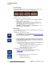
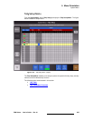
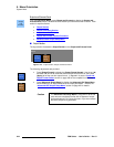
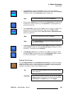
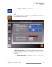
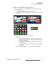
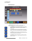
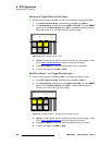
• Red indicates that the mapped input has an “LOS” or “Invalid Signal” error. In
this situation, the input’s
Programmable Display turns red, and the red “Error”
button appears in the top right corner of the
Touch Screen. Press the {Error}
button to learn more. Refer to the “
Notes and Error Messages” section on
page 143 for details.
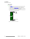
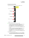
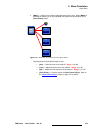
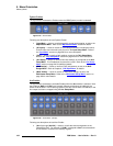
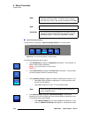
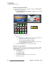
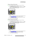
• Yellow indicates that the input is un-mapped, and a signal is present.
• White indicates that the input is un-mapped, and no input signal has been
detected.
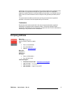
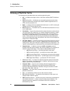
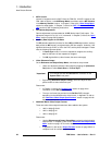
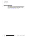
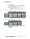
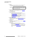
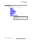
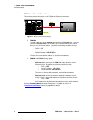
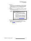
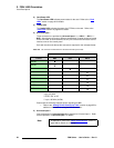
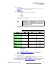
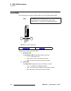
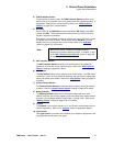
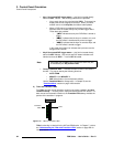
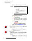
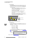
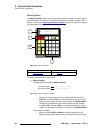
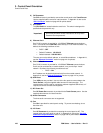
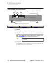
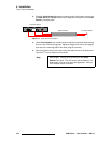
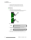
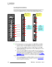
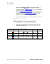
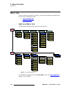
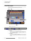
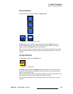
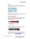
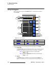
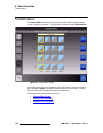
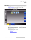
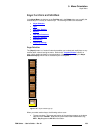
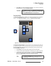
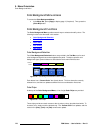
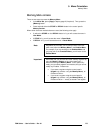
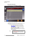
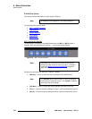
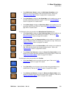
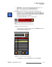
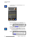
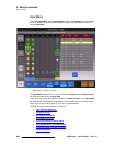
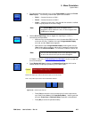
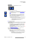
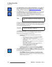
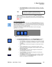
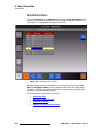
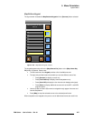
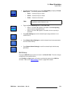
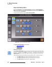
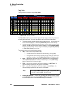
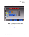
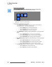
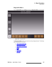
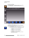
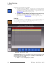
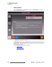
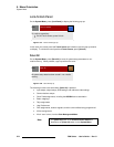
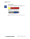
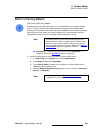
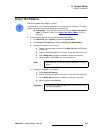
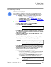
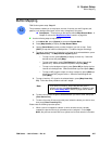
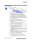
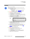
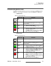
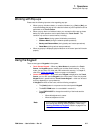
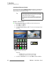
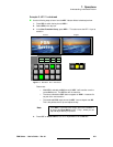
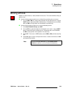
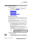
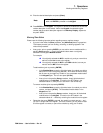
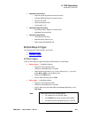
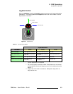
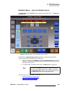
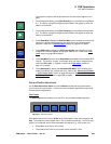
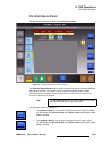
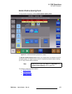
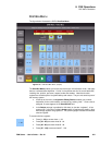
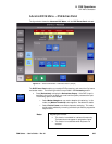
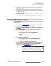
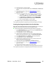
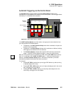
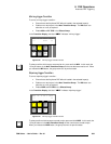
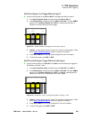
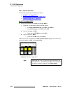
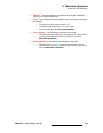
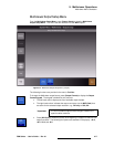
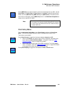
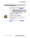
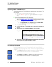
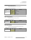
The above “color” information is always available on the
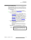
Input Menu and External DSK
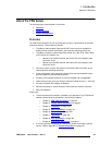
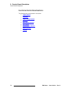
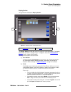
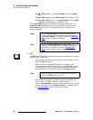
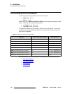
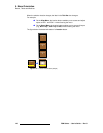
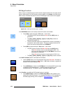
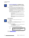
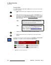
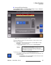
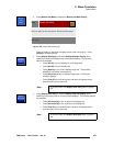
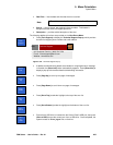
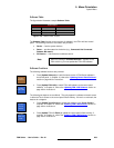
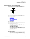
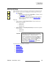
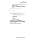
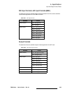
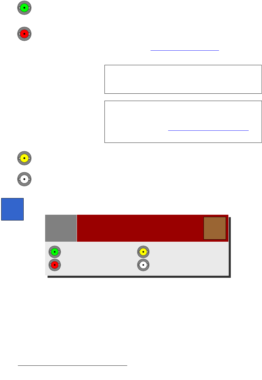
Setup Menu. Press {Info} to display the Input Color Legend Pop-up:
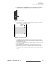
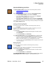
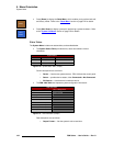
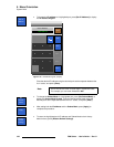
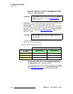
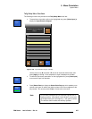
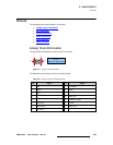
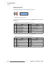
Figure 5-83. Input Color Legend pop-up
Note
For the input connectors on the NIC and UIC, this “red”
condition only occurs if the input has been mapped to the
panel, and the signal was previously OK.
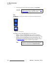
Note
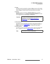
If desired, use the {Error Reporting} button to turn the red
error message off, and return the
Programmable Display to
green. In this mode, the connector remains red. In
Chapter 7, refer to the “
Understanding Error Messages”
section on page 316 for full details.
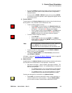
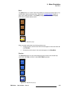
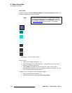
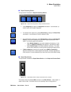
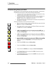
Info
Slot 1, Input 8:
Input color legend
Close
Note
Input mapped, signal OK
Input mapped, error or no signal
Input un-mapped, signal present
Input un-mapped, no signal