122 FSN Series • User’s Guide • Rev 01
4. Installation
Signal Connections
lìíéìí=`çååÉÅíáçåë
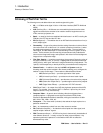
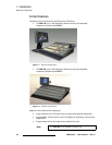
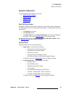
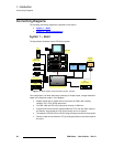
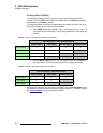
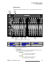
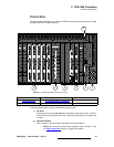
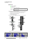
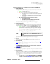
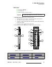
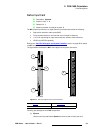
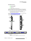
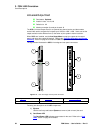
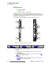
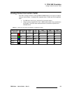
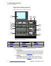
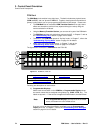
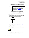
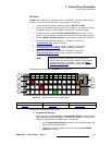
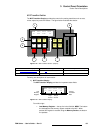
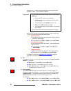
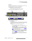
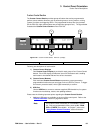
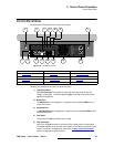
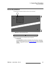
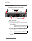
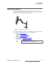
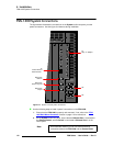
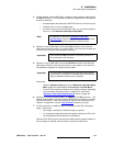
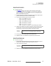
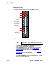
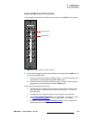
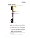
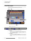
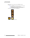
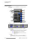
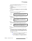
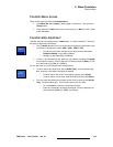
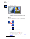
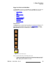
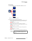
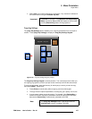
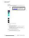
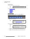
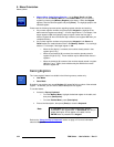
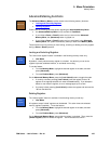
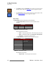
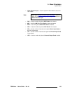
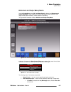
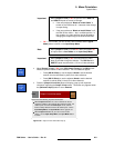
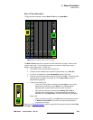
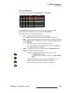
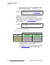
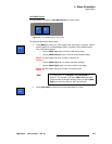
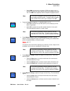
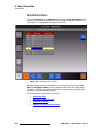
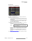
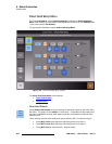
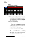
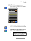
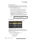
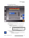
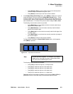
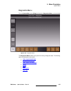
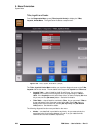
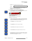
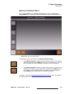
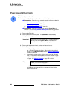
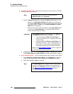
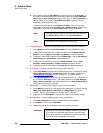
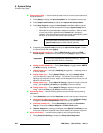
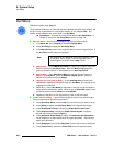
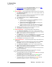
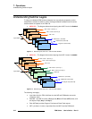
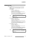
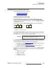
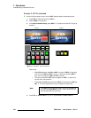
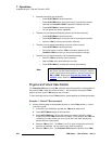
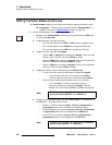
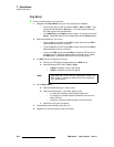
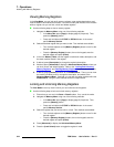
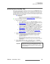
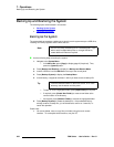
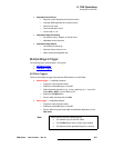
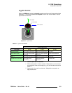
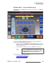
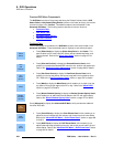
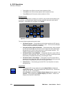
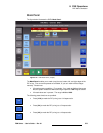
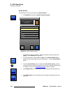
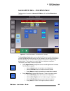
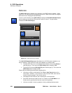
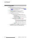
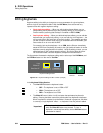
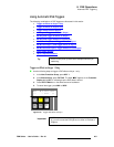
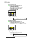
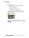
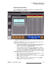
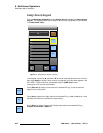
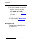
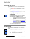
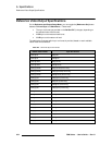
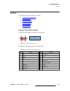
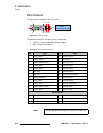
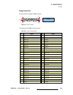
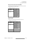
The figure below illustrates the output connections on the M/E card’s rear panel:
Figure 4-15. Output connections
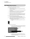
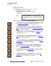
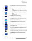
Use the following steps to connect the FSN-1400’s main Program outputs:
1. The Program Out 1 and Program Out 2 signals are identical. Connect to a
monitor, and to your target destination device as required.
2. Connect Preview Out to a monitor. This output provides the Program bank’s
“lookahead” preview video. In Chapter 7, refer to the “Understanding
Lookahead Preview” section on page 319 for additional information.
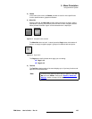
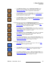
3. Connect Clean Out to a monitor or the desired destination. This output provides
the system’s main clean feed signal. In Chapter 2, refer to the “Clean Feed
Output Selection” section on page 52 for details.
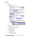
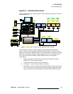
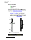
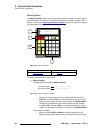
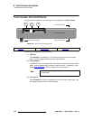
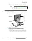
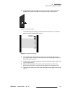
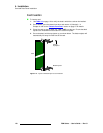
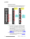
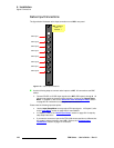
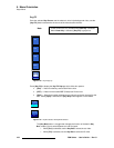
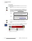
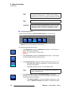
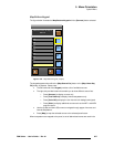
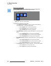
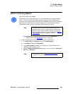
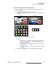
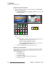
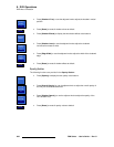
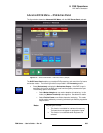
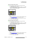
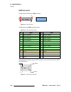
Use the following steps to connect the FSN-1400’s M/E 1 outputs:
1. Connect M/E 1 Program Out to a monitor or the desired destination. This output
provides M/E 1’s program output signal.
2
CLN
Fill
PVW
PVW
PGM
CLN
1
PGM
CLN
3
4
5
6
M/E 2
CutPVW
M/E 1
AUX
DSK
PGM
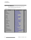
Program Out 2
Program Out 1
Preview Out
Clean Out
M/E 1 Program Out
M/E 1 Preview Out
M/E 1 Clean Out
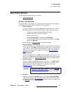
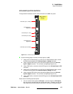
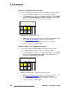
M/E 2 Program Out
M/E 2 Preview Out
M/E 2 Clean Out
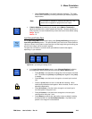
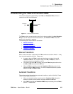
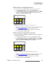
Note
All connections use BNC cables. All outputs are SDI (either
SD-SDI or HD-SDI).