


FSN Series • User’s Guide • Rev 01 311
7. Operations
Understanding Button Color
råÇÉêëí~åÇáåÖ=_ìííçå=`çäçê
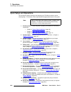
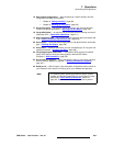
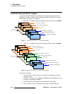
The tables in this section explain the use of color on the buttons in the M/E bank and the
PGM bank. The rules apply to the buttons on each bank’s PGM, PST and KEY buses.
• PGM Bank Rules
• M/E Bank Rules
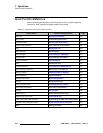
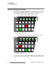
Table 7-1. PGM bank button rules
Button Color Description
Off The button is not mapped.
Dim Amber The button is mapped but not selected. Brightness in this state is
set by the Control Panel Backlight function on the User
Preference Menu.
Green
• The button is selected on PST.
• The bus is not contributing to PGM bank output.
Red
• The button is selected on PGM, which always contributes
to the output of the bank.
• The button is selected on PST, and the bus is contributing
to the PGM bank output — e.g, during a mix or a wipe.
• Note: The button is dim red when FTB is on.
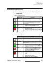
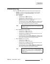
Table 7-2. M/E bank button rules
Button Color Description
Off The button is not mapped.
Dim Amber The button is mapped but not selected. Brightness level in this
state is set by the Control Panel Backlight function on the User
Preference Menu.
Green
• The button is selected on the M/E’s PST and/or KEY bus.
• The bus is not contributing to the output of the M/E bank or
the PGM bank (via re-entry).
Coral
• The button is selected on the M/E’s BG and/or KEY bus,
and the bus is contributing to the M/E bank’s output only.
• The button is selected on the M/E’s PST bus, and the bus
is contributing to the M/E bank’s output only — for
example, during a mix or a wipe.
Red
• The button is selected on the M/E’s BG and/or KEY bus,
and the bus is contributing to the PGM bank’s output via
re-entry.
• The button is selected on the M/E’s PST bus, and the bus
is contributing to the PGM bank’s output via re-entry — for
example, during a mix or a wipe.
• Note: The button is dim red when FTB is on.