


3 - 26
Chapter 3 Specifications and Functions
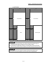
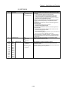
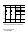
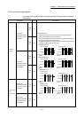
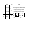
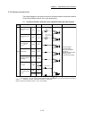
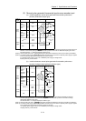
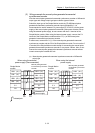
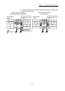
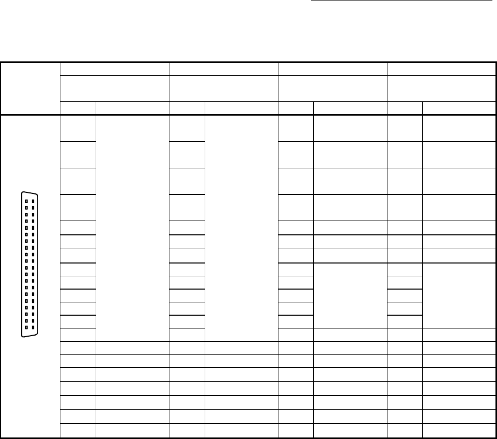
The signal layout for the external input connection connector of Simple Motion module
is shown.
Pin layout
AX4 AX3 AX2 AX1
Axis 4
(External input signal 4)
Axis 3
(External input signal 3)
Axis 2
(External input signal 2)
Axis 1
(External input signal 1)
Pin No. Signal name Pin No. Signal name Pin No. Signal name Pin No. Signal name
B20
B19
B18
B17
B16
B15
B14
B13
B12
B11
B10
B9
B8
B7
B6
B5
B4
B3
B2
B1
A20
A19
A18
A17
A16
A15
A14
A13
A12
A11
A10
A9
A8
A7
A6
A5
A4
A3
A2
A1
Front view o
f
the module
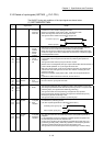
2B20
No connect
(Note-7)
2A20
No connect
(Note-7)
1B20
HB
(Note-3),
(Note-4), (Note-5)
1A20
5V
(Note-9)
2B19 2A19 1B19
HA
(Note-3),
(Note-4), (Note-5)
1A19
5V
(Note-9)
2B18 2A18 1B18
HBL
(Note-3),
(Note-4), (Note-6)
1A18
HBH
(Note-3),
(Note-4), (Note-6)
2B17 2A17 1B17
HAL
(Note-3),
(Note-4), (Note-6)
1A17
HAH
(Note-3),
(Note-4), (Note-6)
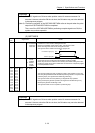
2B16 2A16 1B16
No connect
(Note-7)
1A16
No connect
(Note-7)
2B15 2A15 1B15
5V
(Note-10)
1A15
5V
(Note-10)
2B14 2A14 1B14
SG
(Note-10)
1A14
SG
(Note-10)
2B13 2A13 1B13
No connect
(Note-7)
1A13
No connect
(Note-7)
2B12 2A12 1B12 1A12
2B11 2A11 1B11 1A11
2B10 2A10 1B10 1A10
2B9 2A9 1B9 1A9
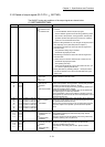
2B8 1B8 EMI. COM 1A8 EMI
2B7 COM 2A7 COM 1B7 COM 1A7 COM
2B6 COM 2A6 COM 1B6 COM 1A6 COM
2B5
DI4
(Note-8)
2A5
DI3
(Note-8)
1B5
DI2
(Note-8)
1A5
DI1
(Note-8)
2B4 STOP
(Note-8)
2A4 STOP
(Note-8)
1B4 STOP
(Note-8)
1A4 STOP
(Note-8)
2B3
DOG
(Note-8)
2A3
DOG
(Note-8)
1B3
DOG
(Note-8)
1A3
DOG
(Note-8)
2B2
RLS
(Note-8)
2A2
RLS
(Note-8)
1B2
RLS
(Note-8)
1A2
RLS
(Note-8)
2B1
FLS
(Note-8)
2A1
FLS
(Note-8)
1B1
FLS
(Note-8)
1A1
FLS
(Note-8)
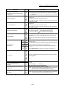
(Note-1) : Pin No. "1_ _ _" indicates the pin No. for the right connector. Pin No. "2_ _ _" indicates the pin No. for the left connector.
(Note-2) : For QD77MS2 does not have AX3 and AX4 connector of the left side.
(Note-3) : Input type from manual pulse generator/incremental synchronous encoder is switched in "[Pr.89] Manual pulse
generator/Incremental synchronous encoder input type selection". (Only the value specified against the axis 1 is valid.)
• 0: Differential-output type
• 1: Voltage-output/open-collector type (Default value)
(Note-4) : Set the signal input form in "[Pr.24] Manual pulse generator/Incremental synchronous encoder input selection".
(Note-5) : Voltage-output/open-collector type
Connect the A-phase/PLS signal to HA, and the B-phase/SIGN signal to HB.
(Note-6) : Differential-output type
Connect the A-phase/PLS signal to HAH, and the A-phase/PLS inverse signal to HAL.
Connect the B-phase/SIGN signal to HBH, and the B-phase/SIGN inverse signal to HBL.
(Note-7) : Do not connect to any of the terminal explained as "No connect".
(Note-8) : Set the external command signal [DI, FLS, RLS, DOG, STOP] in "[Pr.80] External input signal selection" and "[Pr.95] External
command signal selection" at QD77MS16 use.
(Note-9) : Do not connect wires other than the signal wires of the manual pulse generator to 1A20 and 1A19.
(Note-10): Do not use 1A(B)15 and 1A(B)14 for other than the power supply of manual pulse generator.