


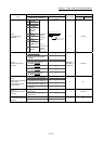
5 - 30
Chapter 5 Data Used for Positioning Control
Item
Setting value, setting range
Default value
Buffer memory address
Value set with GX Works2
Value set with sequence
program
QD77MS2
QD77MS4
QD77MS16
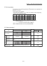
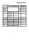
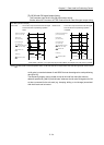
[Pr.22]
Input signal logic
selection
b0 Lower limit
0: Negative
logic
1: Positive
logic
(Note-1):
Only the value
specified
against the
axis 1 is valid.
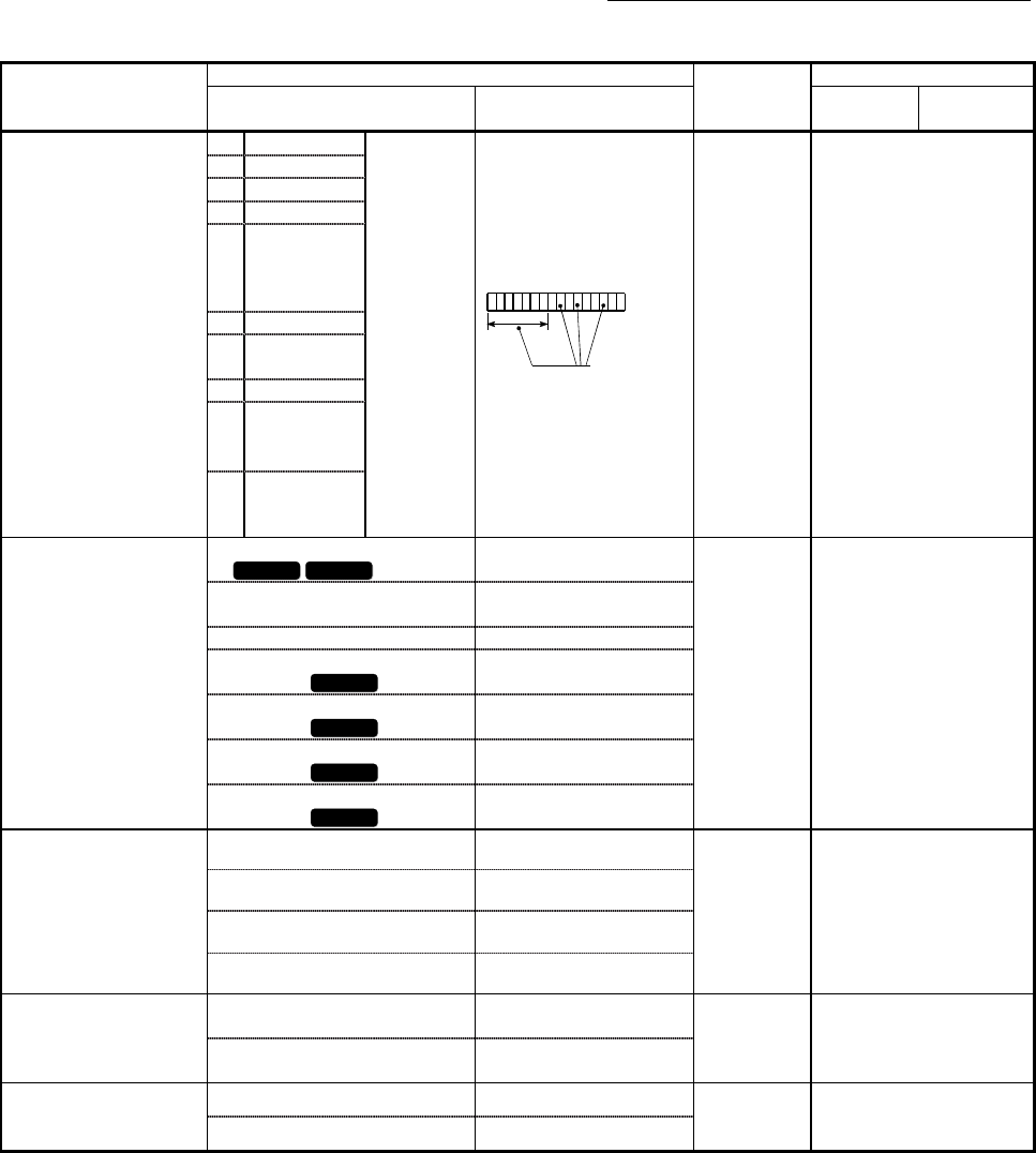
b0123456789101112131415
Always "0" is set to
the part not used.
0 31+150n
b1 Upper limit
b2 Not used
b3 Stop signal
b4
External
command/
switching
signal
b5 Not used
b6
Near-point dog
signal
b7 Not used
b8
Manual pulse
generator input
(Note-1)
b9
to
b15
Not used
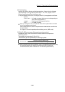
[Pr.80]
External input signal
selection
0: External input signal of QD77MS
QD77MS2 QD77MS4
0
QD77MS2 : 0
QD77MS4 : 0
QD77MS16: 1
32+150n
1: External input signal of servo
amplifier
1
2: Buffer memory of QD77MS 2
3: External input signal 1 of
QD77MS
QD77MS16
3
4: External input signal 2 of
QD77MS
QD77MS16
4
5: External input signal 3 of
QD77MS
QD77MS16
5
6: External input signal 4 of
QD77MS
QD77MS16
6
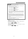
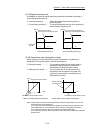
[Pr.24]
Manual pulse generator/
Incremental
synchronous encoder
input selection
0: A-phase/B-phase multiplied by 4 0
0 33
1: A-phase/B-phase multiplied by 2 1
2: A-phase/B-phase multiplied by 1 2
3: PLS/SIGN 3
[Pr.81]
Speed-position function
selection
0: Speed-position switching control
(INC mode)
0
0 34+150n
2: Speed-position switching control
(ABS mode)
2
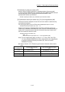
[Pr.82]
Forced stop valid/invalid
selection
0: Valid 0
0 35
1: Invalid 1
n: Axis No.-1