A - 24
MANUAL PAGE ORGANIZATION
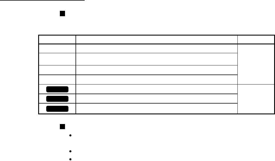
The symbols used in this manual are shown below.
The following symbols represent the buffer memories supported for each axis.
(A serial No. is inserted in the "*" mark.)
Symbol Description Reference
[Pr. * ]
Symbol that indicates positioning parameter and OPR parameter item.
Chapter 5
[Da. * ]
Symbol that indicates positioning data, block start data and condition
data item.
[Md. * ]
Symbol that indicates monitor data item.
[Cd. * ]
Symbol that indicates control data item.
QD77MS2
Symbol that indicates correspondence to only QD77MS2.
—
QD77MS4
Symbol that indicates correspondence to only QD77MS4.
QD77MS16
Symbol that indicates correspondence to only QD77MS16.
Representation
of numerical values used in this manual.
Buffer memory addresses, error codes and warning codes are represented in
decimal.
X/Y devices are represented in hexadecimal.
Setting data and monitor data are represented in decimal or hexadecimal. Data
ended by "H" or "h" is represented in hexadecimal.
(Example) 10.........Decimal
10H......Hexadecimal


