


3 - 32
Chapter 3 Specifications and Functions
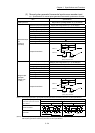
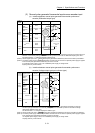
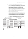
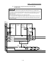
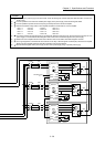
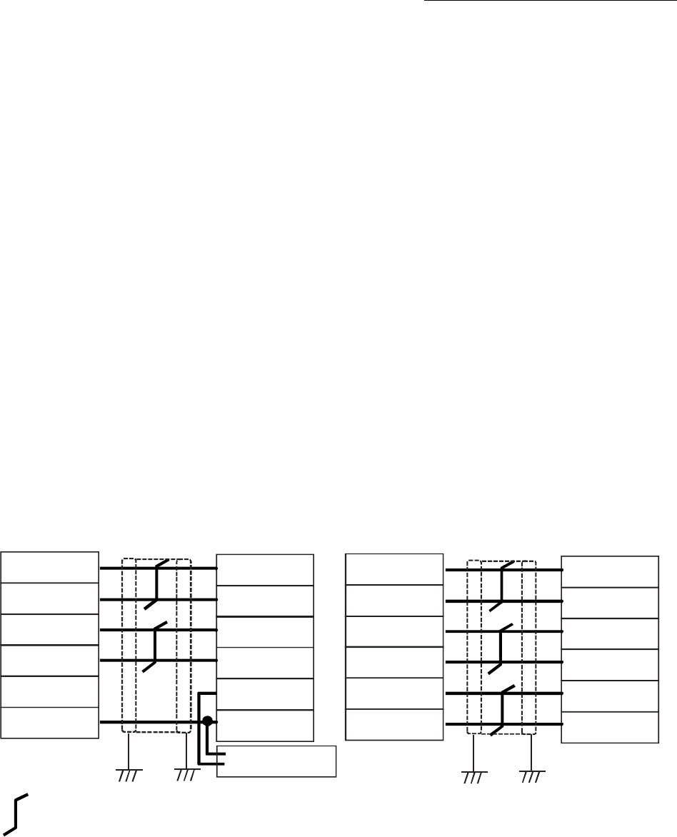
(3) Wiring example for manual pulse generator/incremental
synchronous encoder
Wire the manual pulse generator/incremental synchronous encoder of differential
output type and voltage output type/open-collector type as follows.
Switch the input type of the Simple Motion module by "[Pr.89] Manual pulse
generator/Incremental synchronous encoder input type selection". It is
recommended to use the external 5 V power supply (5 V DC±5%) for the power
supply of the manual pulse generator/incremental synchronous encoder. When
using the external power supply, do not connect with the 5 V terminal of the
Simple Motion module. When using the internal power supply, connect the 5 V
terminal of the Simple Motion module and the 5 V (+) of the manual pulse
generator/ incremental synchronous encoder.
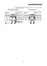
In either case, connect the 0 V (-) of the manual pulse generator/incremental
synchronous encoder and the SG of the Simple Motion module. Do not use the 5
V terminal of the Simple Motion module except for connecting the manual pulse
generator/incremental synchronous encoder. It may cause a failure. Also, do not
connect the manual pulse generator/incremental synchronous encoder whose
current consumption exceeds 200 mA.
(a) Manual pulse generator/Incremental synchronous encoder of differential
output type
FG
FG
Simple Motion
module
HAH (A+)
HAL (A-)
HBH (B+)
HBL (B-)
5 V
SG
HAH (A+)
HAL (A-)
HBH (B+)
HBL (B-)
5 V
0 V
When using the internal
Manual pulse generator/
Incremental synchronous
Manual pulse generator/
Incremental synchronous
Shield
encoder
FG
FG
Simple Motion
module
HAH (A+)
HAL (A-)
HBH (B+)
HBL (B-)
5 V
SG
HAH (A+)
HAL (A-)
HBH (B+)
HBL (B-)
5 V
0 V
External 5 V
Twisted pair
Shield
encoder
power supply
power supply
When using the external
power supply (Recommended)