


14 - 38
Chapter 14 Common Functions
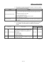
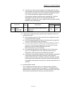
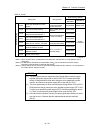
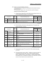
[MR-J4-_B use]
Setting item Setting details
Buffer memory address
QD77MS2
QD77MS4
QD77MS16
Input/output setting
PA04
Forced stop deceleration function
selection
Disable deceleration stop
function at the master
axis and slave axis.
30104+200n 28404+100n
PD15
Driver communication setting
Set the master axis and
slave axis.
30210+200n
Set with
GX Works2
PD16
Driver communication setting
Master transmit data selection 1
Set the transmitted data
at master axis setting.
30211+200n
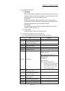
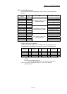
PD17
Driver communication setting
Master transmit data selection 2
30212+200n
PD20
Driver communication setting
Master axis No. selection 1 for slave
Set the axis No. of master
axis at slave axis setting.
30215+200n
PD30
Master-slave operation - Torque
command coefficient on slave
Set the parameter at
slave axis setting.
30225+200n
PD31
Master-slave operation - Speed limit
coefficient on slave
30226+200n
PD32
Master-slave operation - Speed limit
adjusted value on slave
30227+200n
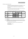
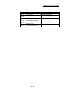
n: Axis No.-1
(Note-1): When the slave axis is not allocated for the master axis, the operation is normal operation only of
master axis.
(Note-2): For QD77MS16, the above servo parameters of PD
are not allocated to the buffer memory.
Write them to Simple Motion module with GX Works2.
(Note-3): At slave setting, set only "Driver communication setting Master axis No. selection 1 for slave (PD20)" in
the master axis No. selection normally.
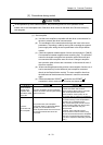
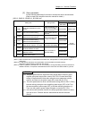
POINT
(1) The servo parameters are transmitted from Simple Motion module to servo
amplifier after power supply ON or reset of PLC CPU. Execute flash ROM
writing of Simple Motion module after writing the servo parameter to buffer
memory, and then turn the power supply ON or reset the PLC CPU.
(2) The servo parameters for driver communication setting (PA04, PD15 to PD17,
PD20) become valid by turning the servo amplifier's power supply OFF to ON.
Turn the servo amplifier's power supply OFF to ON after executing the above
(1). Then, turn the system's power supply ON or reset the PLC CPU.
(3) In the driver communication function, the torque generation direction for slave
axis can be set in "Rotation direction selection/travel direction selection
(PA14)".