13 - 19
Chapter 13 Control Sub Functions
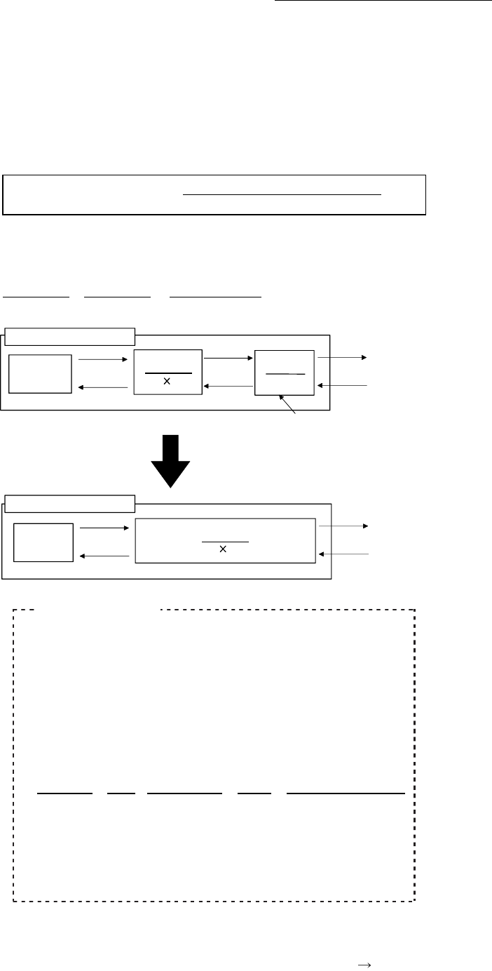
[2] The method for compensating the error
When the position control is carried out using the "Electronic gear" set in a
parameter, this may produce an error between the command movement amount
(L) and the actual movement amount (L'). With Simple Motion module, this error
is compensated by adjusting the electronic gear. The "Error compensation
amount", which is used for error compensation, is defined as follows:
Error compensation amount =
Command movement amount (L)
…(2)
Actual movement amount (L')
The electronic gear including an error compensation amount is shown
below.
AP
L
=
AP'
AL
AM L' AL'
AM'
Command
value
Control
unit
AP
AL AM
L
L'
PLS
Servo
amplifier
Simple Motion module
AP'
AL' AM'
Control
unit
Command
value
PLS
Servo
amplifier
1 if there is no error (in regular case)
Electronic gear taking an error
into consideration
Simple Motion module
Calculation example
(Conditions)
Number of pulses per rotation (AP) : 4194304 [PLS]
Movement amount per rotation (AL)
: 5000.0 [
m]
Unit magnification (AM) : 1
Positionin
results
Command movement amount (L)
Actual movement amount (L')
: 100 [mm]
: 101 [mm]
Com
ensation value
AP
L
=
4194304
100
=
4194304 (AP')
AL
AM
L'
5000.0
1
101
5050
(AL')
1(AM')
Number of pulses per rotation (AP')
: 4194304 …[Pr.2]
Movement amount per rotation (AL')
: 5050.0 ….[Pr.3]
Unit magnification (AM')
: 1 ………...[Pr.4]
Set the post-compensation "[Pr.2] Number of pulses per rotation (AP')",
"[Pr.3] Movement amount per rotation (AL')", and "[Pr.4] Unit magnification
(AM')" in the parameters, and write them to the Simple Motion module.
The set details are validated at the rising edge (OFF
ON) of the PLC
READY signal [Y0].


