12 - 9
Chapter 12 Expansion Control
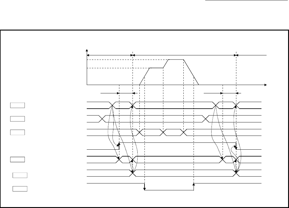
The following chart shows the operation timing for axis 1.
[QD77MS4 operation example]
Zero speed
( Servo status: b3)Md.108
0 10 10
0 10 0
0 20000 030000
0 3130
30
0
[0, 0]
OFF
ON
[1, 0] [0, 0]
t
V
Control mode
( Servo status: b2, b3)Md.108
ON
OFF
30000
20000
6 to 11ms
6 to 11ms
BUSY signal [XC]
Axis operation status
Md.26
Cd.140
Cd.139
Cd.138 Control mode switching
request
Control mode setting
Command speed at speed
control mode
Position control mode Speed control mode Position control mode
0
(Note): Refer to Section 3.3 for input/output signal of QD77MS16 and Chapter 5 for buffer memory address.


