


5 - 6
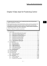
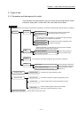
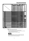
Chapter 5 Data Used for Positioning Control
Control
Positioning parameter
OPR control
Major positioning control Manual control
Expansion
control
Related sub function
Position control
1 to 4 axis speed control
Speed-position or position-speed control
Other control
Manual pulse generator operation
Inching operation
JOG operation
Speed-torque control
1-axis linear control
2/3/4-axis linear interpolation control
1-axis fixed-feed control
2/3/4-axis fixed-feed control
2-axis circular interpolation control
Current value changing
JUMP instruction, NOP instruction,
LOOP to LEND
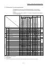
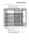
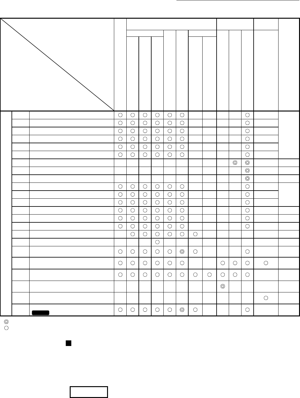
Detailed parameters 2
[Pr.25]
Acceleration time 1
– – – –
–
13.7.6
[Pr.26]
Acceleration time 2
– – – –
–
[Pr.27] Acceleration time 3 – – – –
–
[Pr.28] Deceleration time 1 – – – –
–
[Pr.29]
Deceleration time 2
– – – –
–
[Pr.30]
Deceleration time 3
– – – –
–
[Pr.31] JOG speed limit value – – – – – – – – –
– 13.4.1
[Pr.32] JOG operation acceleration time selection – – – – – – – – – –
– –
[Pr.33]
JOG operation deceleration time selection – – – – – – – – – –
– –
[Pr.34]
Acceleration/deceleration process selection
– – – –
–
13.7. 6
[Pr.35] S-curve ratio – – – –
–
[Pr.36] Sudden stop deceleration time – – – –
–
[Pr.37]
Stop group 1 sudden stop selection
– – – –
– –
[Pr.38]
Stop group 2 sudden stop selection
– – – –
– –
[Pr.39] Stop group 3 sudden stop selection – – – –
– –
[Pr.40] Positioning complete signal output time – – – – – – –
[Pr.41]
Allowable circular interpolation error width – – –
– – – – – – – – –
[Pr.42]
External command function selection
– – –
–
13.5.1
13.7.2
[Pr.83]
Speed control 10 x multiplier setting for
degree axis
–
–
13.7.10
[Pr.84]
Restart allowable range when servo OFF
to ON
–
5.2.4
[Pr.89]
Manual pulse generator/Incremental
synchronous encoder input type selection
– – – – – – – –
– – –
5.2.4
[Pr.90]
Operation setting for speed-torque control
mode
– – – – – – – – – – –
12.1
[Pr.95]
External command signal selection
QD77MS16
– – –
–
–
: Always set
: Set as required ("–" when not required)
– : Setting not required (The setting value is invalid. When the value is the default value or within the setting range, there is no problem.)
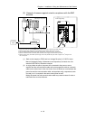
Checking the positioning parameters
[Pr.1] to [Pr.90], [Pr.95] are checked with the following timing.
When the "PLC READY signal [Y0]" output from the PLC CPU to the Simple
Motion module changes from OFF to ON.
When the positioning test of GX Works2 is executed.
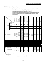
REMARK
"High-level positioning control" is carried out in combination with the "major
positioning control".
Refer to the "major positioning control" parameter settings for details on the
parameters required for "high-level positioning control".