11 - 31
Chapter 11 Manual Control
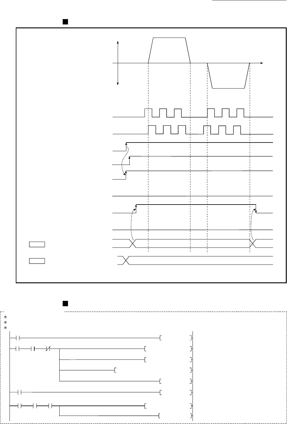
Start time chart
[QD77MS4 operation example]
Pulse input A phase
OFF
ON
OFF
OFF
1
t
OFF
00
1
Forward run
Reverse run
ON
Pulse input B phase
BUSY signal
READY signal
PLC READY signal
Start complete signal
Error detection signal
[Y0]
[X0]
[X10]
[XC]
[X8]
Cd. 21 Manual pulse generator
enable flag
Cd. 20 Manual pulse generator
1 pulse input magnification
OFF
ON
All axis servo ON
[Y1]
OFF
ON
(Note): Refer to Section 3.3 for input/output signal of QD77MS16.
Fig. 11.18 Manual pulse generator operation start time chart
Creating the program
[QD77MS4 program example]
No.13 Manual pulse generator operation program
<Pulsate manual pulse generator operation command>
<Set manual pulse generator input scale per pulse>
<Write manual pulse generator operation enable>
<Write data for manual pulse generator>
<Turn ON manual pulse generator operating flag>
<Pulsate manual pulse generator operation disable
command>
<Write manual pulse generator operation disable>
<Turn OFF manual pulse generator operating flag>
X30
301
PLS M8
M8
308
X0 X0C
DMOVP K1 D8
MOVP K1 D10
TOP H0 K3D8K1522
SET M9
M10
330
M9 X0C
MOVP K0
U0\
G1524
RST M9
326
X31
PLS M10


