13 - 84
Chapter 13 Control Sub Functions
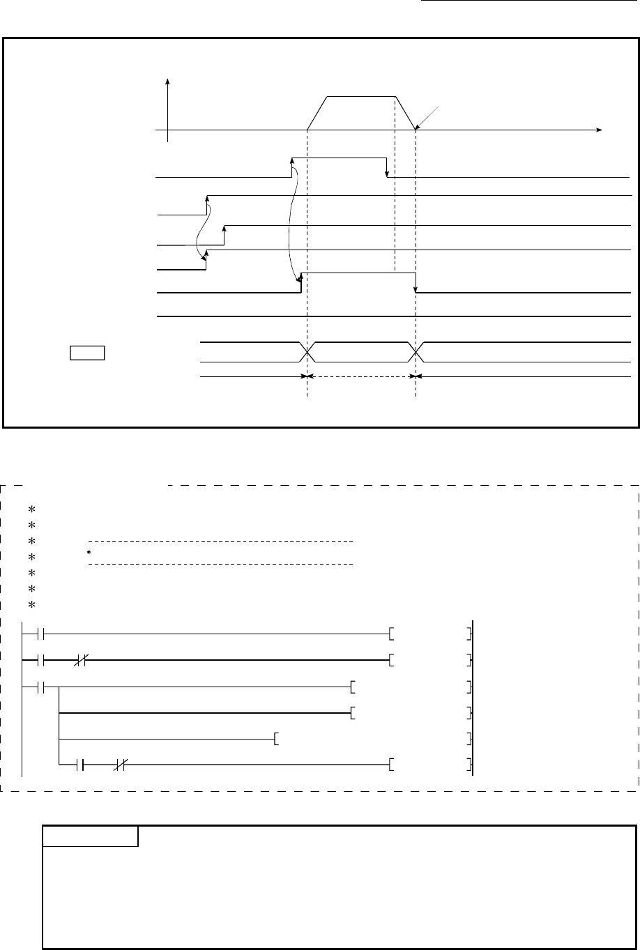
[QD77MS4 operation example]
A
ll axis servo ON
READY signal
V
t
Target position
BUSY signal
[X8]
n2n1 nx
Md.20 Current feed value
Error detection signal
[XC]
[X0]
[Y1]
[Y8]
PLC READY signal
[Y0]
Teaching is possible Teaching is possibleTeaching is impossible
Forward run JOG start
signal
(Note): Refer to Section 3.3 for input/output signal of QD77MS16.
2) Carry out the teaching operation with the following program.
No.20 Teaching program
Position to the target position with manual operation.
<Pulsate teaching command>
<Hold teaching command>
<Set teaching data>
<Set positioning data No.>
<Execute teaching>
<Turn OFF teaching command
memory>
M19PLS
ZP.TEACH1 "U0" D33 M34
477
488
492
M20
H0MOVP D35
M20SET
K3MOVP D36
M20RST
M19
X39
X0C
M34 M35
[QD77MS4 program example]
POINT
(1) Confirm the teaching function and teaching procedure before setting the positioning data.
(2) The positioning addresses that are written are absolute address (ABS) values.
(3) The positioning data written by the teaching function overwrites the data of the buffer
memory only. Therefore, read from the buffer memory and write to the flash ROM before
turning the power OFF as necessary.


