


3 - 11
Chapter 3 Specifications and Functions
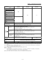
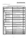
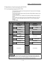
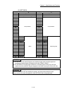
3.2.4 QD77MS common functions
The outline of the functions executed as necessary is described below.
(Refer to "Section 2" for details on each function.)
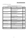
Common functions Details
Reference
section
Parameter initialization function
This function returns the "parameters" stored in the buffer
memory/internal memory and flash ROM/internal memory
(nonvolatile) of Simple Motion module to the default values.
The following two methods can be used.
1) Method using sequence program
2) Method using GX Works2
14.2
Execution data backup function
This function stores the "setting data", currently being executed,
into the flash ROM/internal memory (nonvolatile).
1) Method using sequence program
2) Method using GX Works2
14.3
External signal selection function
This function selects from the following signals when using the
upper/lower limit signal, the near-point dog signal, and the stop
signal.
• External input signal of QD77MS
• External input signal of servo amplifier
• External input signal via CPU (buffer memory of QD77MS)
14.4
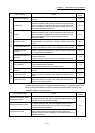
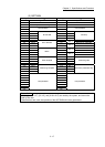
External I/O signal logic switching function
This function switches I/O signal logic according to externally
connected devices.
This function enables the use of the system that does not use b
(N.C.)-contact signals, such as Upper/lower limit signal, by
setting parameters to positive logic.
14.5
History monitor function
This function monitors errors, warnings, and start history of all
axes.
14.6
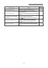
Amplifier-less operation function
This function executes the positioning control of Simple Motion
module without connecting to the servo amplifiers.
It is used to debug the program at the start-up of the device or
simulate the positioning operation.
14.7
Virtual servo amplifier function
This function executes the operation as the axis (virtual servo
amplifier axis) that operates only command (instruction) virtually
without servo amplifiers.
14.8
Driver communication function
This function uses the "Master-slave operation function" of servo
amplifier. The Simple Motion module controls the master axis
and the slave axis is controlled by data communication between
servo amplifiers (driver communication) without Simple Motion
module.
14.9
Mark detection function
This function is used to latch any data at the input timing of the
mark detection signal (DI1 to DI4).
14.10