


3 - 21
Chapter 3 Specifications and Functions
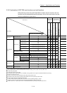
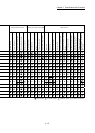
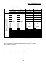
3.3.3 Details of output signals (PLC CPU QD77MS)
The ON/OFF timing and conditions of the output signals are shown below.
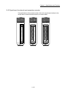
(1) QD77MS2/QD77MS4
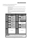
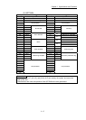
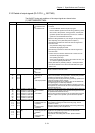
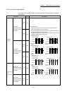
Device No. Signal name Details
Y0 PLC READY OFF:
PLC READY OFF
ON:
PLC READY ON
(a) This signal notifies the Simple Motion module that the PLC CPU
is normal.
• It is turned ON/OFF with the sequence program.
• The PLC READY signal is turned ON during positioning control,
OPR control, JOG operation, inching operation, manual pulse
generator operation and speed-torque control ,etc. unless the
system is in the GX Works2 test function.
(b) When the data (parameter etc.) are changed, this signal is turned
OFF depending on the parameter (Refer to Chapter 7.).
(c) The following processes are carried out when this signal turns
from OFF to ON.
• The parameter setting range is checked.
• The READY signal [X0] turns ON.
(d) The following processes are carried out when this signal turns
from ON to OFF.
In these cases, the OFF time should be set to 100ms or more.
• The READY signal [X0] turns OFF.
• The operating axis stops.
• The M code ON signal [X4 to X7] for each axis turns OFF, and
"0" is stored in "[Md.25] Valid M code".
(e) When parameters or positioning data (No. 1 to 600) are written
from the GX Works2 or PLC CPU to the flash ROM, this signal
will turn OFF.
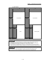
Y1 All axis servo ON OFF:
Servo OFF
ON:
Servo ON
• The servo for all the servo amplifiers connected to the Simple
Motion module is turned ON or OFF.
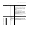
Y4
Y5
Y6
Y7
Axis 1
Axis 2
Axis 3
Axis 4
Axis stop OFF:
Axis stop not
requested
ON:
Axis stop requested
• When the axis stop signal turns ON, the OPR control, positioning
control, JOG operation, inching operation, manual pulse generator
operation and speed-torque control etc. will stop.
• By turning the axis stop signal ON during positioning operation, the
positioning operation will be "stopped".
• Whether to decelerate stop or suddenly stop can be selected with
"[Pr.39] Stop group 3 sudden stop selection".
• During interpolation control of the positioning operation, if the axis
stop signal of any axis turns ON, all axes in the interpolation control
will decelerate and stop.
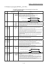
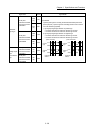
Y8
Y9
YA
YB
YC
YD
YE
YF
Axis 1
Axis 1
Axis 2
Axis 2
Axis 3
Axis 3
Axis 4
Axis 4
Forward run JOG start
Reverse run JOG start
Forward run JOG start
Reverse run JOG start
Forward run JOG start
Reverse run JOG start
Forward run JOG start
Reverse run JOG start
OFF:
JOG not started
ON:
JOG started
• When the JOG start signal is ON, JOG operation will be carried out
at the "[Cd.17] JOG speed". When the JOG start signal turns OFF,
the operation will decelerate and stop.
• When inching movement amount is set, the designated movement
amount is output for one operation cycle and then the operation
stops.
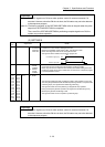
Y10
Y11
Y12
Y13
Axis 1
Axis 2
Axis 3
Axis 4
Positioning start OFF:
Positioning start not
requested
ON:
Positioning start
requested
• OPR operation or positioning operation is started.
• The positioning start signal is valid at the rising edge, and the
operation is started.
• When this signal turns ON during BUSY, the warning "Start during
operation" (warning code: 100) will occur.
Y14
Y15
Y16
Y17
Axis 1
Axis 2
Axis 3
Axis 4
Execution prohibition
flag
OFF:
Not during execution
prohibition
ON:
During execution
prohibition
• If the execution prohibition flag is ON when the positioning start
signal turns ON, positioning control does not start until the
execution prohibition flag turns OFF.
Used with the "Pre-reading start function". (Refer to Section
13.7.7.)