


14 - 42
Chapter 14 Common Functions
[2] How to use mark detection function
The following shows an example for mark detection by the external command
signal (DI2) of axis 2.
The mark detection target is axis 1 real current value, and the all range is
detected in continuous detection mode.
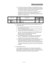
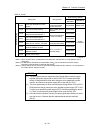
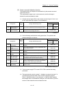
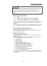
(1) Allocate the input signal (DI2) to the external command signal of axis 2, and
set the "high speed input request" for mark detection.
Storage item
Setting
value
Storage details/storage value
Buffer memory address
QD77MS2
QD77MS4
QD77MS16
[Pr.95]
External command
signal selection
2 Set "2: DI2" to the external command signal of axis 2. —
219
(69+150n)
[Pr.42]
External command
function selection
4
Set "4: High speed input request" as the function used in
the external command signal of axis 2.
212 (62+150n)
n: Axis No.-1
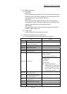
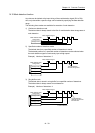
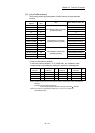
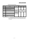
(2) Set the following mark detection setting parameters. The optional mark
detection setting No. can be set.
Storage item
Setting
value
Storage details/storage value
Buffer memory address
QD77MS2
QD77MS4
QD77MS16
[Pr.800]
Mark detection
signal setting
2
Set "2: Axis 2" to the external input signal for mark
detection.
54000+20k
[Pr.801]
Mark detection
signal
compensation time
0
Set "0: (No compensation)" to the compensation time
such as delay of sensor.
54001+20k
[Pr.802]
Mark detection data
type
2
Set "2: Real current value" to the target data for mark
detection.
54002+20k
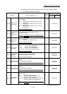
[Pr.803]
Mark detection data
axis No.
1
Set "1: Axis 1" to the axis No. of target data for mark
detection.
54003+20k
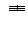
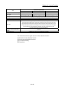
[Pr.805]
Latch data range
upper limit value
0
Set "0" to the valid upper limit value for latch data at
mark detection. (Mark detection for all range is executed
by setting the same value as lower limit value.)
54006+20k
54007+20k
[Pr.806]
Latch data range
lower limit value
0
Set "0" to the valid lower limit value for latch data at mark
detection. (Mark detection for all range is executed by
setting the same value as upper limit value.)
54008+20k
54009+20k
[Pr.807]
Mark detection
mode setting
0
Set "0: Continuous detection mode" to the mark
detection mode.
54010+20k
k: Mark detection setting No.-1
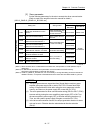
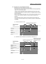
(3) Turn the power supply OFF or reset of PLC CPU to validate the setting
parameters.
(4) The mark detection starts by setting "1: Validates an external command." in
"[Cd.8] External command valid" of axis 2 with the sequence program.
Refer to "[Md.800] Number of mark detection" or "[Md.801] Mark detection
data storage area" of mark detection setting No. set in this section (2) for the
number of mark detections and mark detection data.