13 - 38
Chapter 13 Control Sub Functions
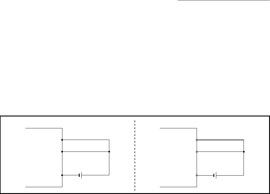
[4] When the hardware stroke limit function is not used
When not using the hardware stroke limit function, wire the terminals of the
QD77MS/servo amplifier upper/lower limit stroke limit as shown in the following
drawing. As for the 24VDC power supply, the direction of current can be switched.
When the logic of FLS and RLS is set to "positive logic" using "[Pr.22] Input
signal logic selection", positioning control can be carried out even if FLS and RLS
of the following signals are not wired.
External input signal of QD77MS
External input signal of servo amplifier
External input signal via CPU (buffer memory of QD77MS)
(For details, refer to Section 14.5 "External I/O signal logic switching function".)
QD77MS
COM
24VDC
FLS
RLS
Servo amplifier
DICOM
24VDC
DI1
(FLS)
DI2
(RLS)
Fig. 13.19 Wiring when not using the hardware stroke limit function
(When "[Pr.22] Input signal logic selection" is the initial value)


