


7 - 17
Chapter 7 Memory Configuration and Data Process
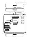
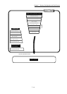
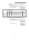
(1) When the servo amplifier's power supply is turned ON before the system's
power supply ON.
(a) When the servo parameter "[Pr.100] Servo series"
"0" is stored in the
internal memory (nonvolatile).
Communication start timing to the servo amplifier: Initialization completion
(Fig. 7.1 (A))
Transfer the servo parameter : The data stored (backed
up) in the internal
memory (nonvolatile).
0 (Standby)
21 (Servo OFF)
20 (Servo amplifier has not been connected/servo amplifier power OFF)
Transfer the servo parameter at this point to the servo amplifier
Communication invalid
During
communication
Communication start (Axis connection)
Md.26
Axis operation
status
Communication
operation status with
servo amplifier
Servo parameter of
buffer memory/internal
memory
Indefinite value
Value of internal memory (nonvolatile)
Initialization
completion
of QD77MS (A)
Buffer memory/
internal memory
data setting
Axis connection completion
QD77MS
power ON
Fig. 7.1 When the servo amplifier had started before the system's power supply ON
(The servo series of internal memory (nonvolatile) is set.)
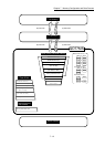
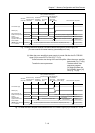
(b) When the servo parameter "[Pr.100] Servo series" = "0" is stored in the
internal memory (nonvolatile).
Communication start timing to the servo amplifier: The data written from
sequence program
before the PLC READY
signal [Y0] ON (Fig. 7.2
(B)).
Transfer the servo parameter : The data written from
sequence program/
GX Works2 before the
PLC READY signal [Y0]
ON (Fig. 7.2 (A)).