


16 - 4
Chapter 16 Troubleshooting
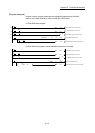
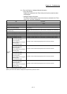
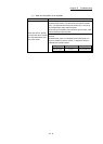
Item Description
QD77MS16
display
• Axis in which the error occurred
(Upper limit signal)
• Axis in which the error occurred
(Lower limit signal)
• Axis in which the error occurred
(Stop signal)
• Axis in which the error occurred
(External command signal/
switching signal)
• Axis in which the error occurred
(Near-point signal)
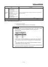
The status of external input signals of the axis in which the error occurred (at error
occurrence) is stored.
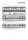
Servo alarm
The alarm code detected by servo amplifier is stored.
(Note-1)
Driver operation alarm
The driver operation alarm detected by servo amplifier is stored.
(Note-2)
(Note-1): "0" is stored unless the servo error occurs.
(Note-2): "0" is stored unless the driver operation alarm occurs.
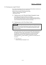
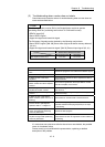
(c) [Create CSV File] button
The module error logs are output to a CSV format file.
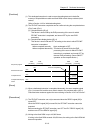
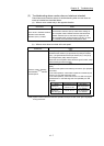
POINT
(1) If errors frequently occur in the Simple Motion module, "*HST.LOSS*" (instead
of an actual error code) may be displayed in the Error Code column.
(Display example)
If "*HST.LOSS*" is frequently displayed, set a larger value for the number of
errors collected per scan in the PLC RAS tab of the PLC Parameter dialog
box.
For the setting, refer to the "User's Manual (Function Explanation, Program
Fundamentals)" of the CPU module in use.
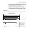
(2) If the error occurred at the simultaneous start, the axis No. in which the error is
detected is stored in the "Starting axis" in Error History.