83
8.11 Monitoring Screen Set-up
Set the information such as the floor name, plan view, operation block, or other items to be monitored/
displayed on the management screen of the integrated centralized control softwareTG-2000A.
8.11.1 Configuration Procedure and Restrictions
Check these points before setting the system configuration.
[Procedure]
1) Click the [Monitoring screen set-up] button.
Click the [Monitoring screen set-up] button in the
User Settings Group in the Initial window.
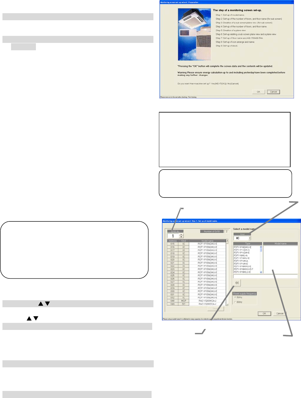
2) Click the [OK] button after checking the display
contents.
Check the information displayed and click the [OK]
button.
* When the [Cancel] button is clicked, this setting is terminated
to return to the initial window.
The monitor display set-ups are done in the following
order.
Step 1 : Set-up of model name.
Step 2 : Set-up of the number of floors, and floor
name (for sub screen)
Step 3 : Creation of a sub screen plane view
(for sub screen)
Step 4 : Set-up of the number of floors, and floor
name.
Step 5 : Creation of a plane view.
Step 6 : Set-up relating a sub screen plane view
and a plane view.
Step 7 : Set-up of floor name and AG-150A/G-50A.
Step 8 : Set-up of icon arrange and name.
Step 9 : Set-up of block
8.11.2 Set-up of model name (Step 1)
Set the model name of the air conditioner unit
(outdoor unit, indoor unit, sub unit, LOSSNAY etc.)
connected to this system.
Setup the unit configuration model name
[Procedure]
1) Click the “
/
” button to select AG-150A/G-50A No.
Select the AG-150A/G-50A No. to be assigned using
the “
/
” buttons.
2) Select the unit to be set.
Click the units for which the same Model Name
is to be set. The selected cells are displayed in
cyan and become the objective of Model Name setup. Each time clicked, the unit is alternately
selected and removed. Multiple units can also be selected.
3) Select the Kind, Type, and Model Name.
Select the Model Name of the unit you want to set from Kind, Type, Class, and Model Name. (Kind:
IC, LC, FU, OC, BC, OS) The Model Name appears at Model Name candidate.
* Refer to Chapter 8.7.3 for details of each model.
4) Click the [Set] button.
When the [Set] button is clicked, the Model Name is reflected as a selected unit Model Name
candidate.
Note:
• The Charge function use this set Model name
data. When the model name is changed, the
data is monitored and control is carried ou
using that data.
• The Model name can be checked during
maintenance.
Set button
Model name candidate
Set-up of model name screen
AG-150A/G-50A
Selection button
Kind selection button
Monitoring screen set-up preparation screen
Note:
• Some screens may not appear depending
on the validity of the functions.
If the “Sub screen function setting” on User setting 1 is
“Deactivate,” the following steps will appear:
Step1: Set-up of model name
Step2: Set-up of the number of floors, and floor name
Step3: Creation of a plane view
Step4: Set-up of floor name and AG-150A/G-50A
Step5: Set-up of icon arrange and name
Step6: Set-up of block
