11
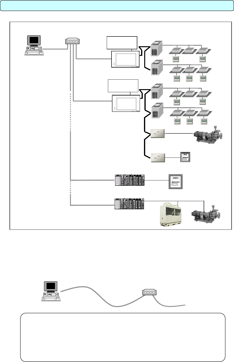
3.1 System Configuration Example
*1: Connect AG-150A/G-50A to a private network. (Only use on the private network.)
Use a security device such as a VPN (Virtual Private Network) router when connecting to the Internet.
*2: Either PLC or PI Controller can be connected to the Measurement meter.
3.2 Hardware Connection Diagram
(1) LAN connection
Connect the LAN cable to the computer. For the location of the LAN connector for the computer,
refer to the Instruction Manual of the computer.
Remot
e
controlle
r
Power
suppl
y
uni
t
Integrated centralized
control softwar
e
TG
-
2000A
HUB
G
-
50
A
G
-
50
A
LAN
Outdoor uni
t
Indoor uni
t
[Image drawing]
Power
suppl
y
uni
t
Monitor status
General Purpose Control PLC
Watt Hour Meter Pulse Count PLC
Measurement Meter
(Electric, Gas, Water,
Amount of Heat)
Pulse
PI controller
Pump
Pulse
DIDO controller
Measurement Meter
(Electric, Gas, Water,
Amount of Heat)
Chiller Pump
3. System Configuration
Note:
• Use a HUB with a repeater or a switch.
• When using a HUB with a repeater, execute the LAN cascade connection as shown
below.
For 10BASE-T, the cascade connection is executable up to a maximum of 4 stages.
For 100BASE-TX, the cascade connection is executable up to a maximum of 2 stages.
*Refer to the HUB Instructions Manual for the maximum connectable number of HUBs.
TG-2000A
HUB
10BASE-
T
or
100BASE-TX
straight cable
LAN
To G-50A
To PLC
*2
*2
*1
A
G-150
A
or G-50A
A
G-150
A
or G-50A


