


12
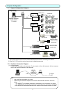
4.1 Flow of Site Adjustment
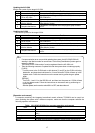
When the task of site adjustment is subdivided into smaller tasks as shown in the figure below, the
tasks can be broadly grouped into four steps. The benefit of following these for steps when carrying
out the tasks of site adjustment is that if troubles do arise, it will be clear which step caused the
problem. This makes it easier to solve problems and this results in a more efficient execution of site
adjustment tasks.
(Step 2 can be skipped when not using the PLC.)
Carry out site adjustment, by following the step by step instructions shown below.
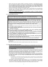
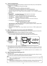
<System example>
4. Flow of Site Adjustment
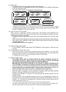
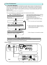
Step 1 AG-150A/G-50A test run
Check that the air conditioners and controllers
are correctly configured and that the air con-
ditioner works.
* Refer to Chapter 4 in this booklet for details.
* For the test operation method of the air conditioner,
DIDO controller, AI controller, PI controller
and central controller AG-150A/G-50A, refer to the
relevant installation manuals.
* Check that only the air conditioner test
operation has been completed before starting
Ste
p
1.
Step 3 PC connections and settings
Connect and set up the software and hard-
ware on the PC with TG-2000A installed.
Check that it is ready for operation.
Step 4 TG-2000A system test run
Check that the TG-2000A man-machine system can correctly operate air conditioner units of all
the managed systems by issuing TG-2000A commands.
Step 2 PLC connections and installation
Connect the PLC and device hardware, and
install the PLC software into the PLC. *1
*1. Refer to the instruction manual for the PLC,
electric amount count software or PLC fo
r
general equipment software.
LAN
Power supply unit
Step 1
Step 4
Step 3
Integrated centralized
control software
TG-2000A
HUB
A
G-150
A
or G-50
A
Step 2
Step 1
PLC
Meters
(electricity, gas,
water, calorific
value
)
Pulse
Status monitor
Chiller Pump
Use PLC?
* If PLC is not used, step 2 can be skipped.
YES
NO