


13
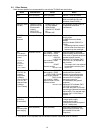
4.2 Tools for Site Adjustment
You will need the following equipment and reference material in order to easily carry out site adjustment.
<Measurement instruments>
• Tester : to check the wiring and the voltage
<Reference material>
• All necessary drawings of the air conditioning control system
• TG-2000A Instruction Manual (Site Adjustment (this manual), Management)
• Instruction Manual and Installation Manual for each air conditioner unit and controller
• Instruction manual for PLC, electric amount count software or PLC for general equipment
software.
<Other material>
• License number : AG-150A/G-50A license number required to use functions
• Floppy disk : used when copying data
• CD-R/USB memory: used to store generated data and copy it to the site PC.
• TG-2000A CD : Integrated centralized control software TG-2000A setup disk
• Initial setting tool : Computer in which this tool is installed
• LAN cable : PAC-YG00FA: LAN cable for connection to the front of G-50A (as
necessary)
• PLC setting tool : GX Developer (Mitsubishi Electric) software
(including the dedicated RS-232-C cable)
*PLC…. Must be installed at site with system using PLC.
• Table setting tool : Table setting tool for PLC for general equipment software (required only
when an interlocking control is performed)
• Screwdriver kit
• Other usual maintenance tools
• Maintenance tool: needed when using interlock control function of DIDO controller and AI
controller.
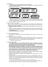
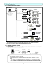
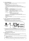
4.3 Step 1: Test operation from central controller AG-150A/G-50A
Perform only the test operation of the air-conditioning system of the central controller AG-150A/G-50A.
(1) Preliminary check
Check that the test operation of the air conditioner has been completed.
Check that the central controller AG-150A/G-50A is set to Group and Interlock.
(The initial setting is executable using the initial setting Web or the AG-150A/G-50A.)
(2) Test operation from central controller AG-150A/G-50A
After supplying power to the central controller AG-150A/G-50A and all air conditioners, perform the
test operation from the central controller AG-150A/G-50A and check the operation state of each
unit.
* For the test operation method, refer to the installation manual for the air conditioner or the
central controller AG-150A/G-50A.
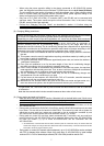
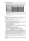
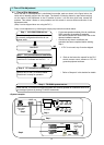
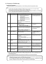
4.4 Step 2 Connecting and installing the PLC
(1) Preliminary check
Check that the PLC has been installed and its power wired, and that the pulse wiring to the watt
hour meter to the wiring to the general equipment has been completed.
Note:
• Refer to the installation manual or instruction manual enclosed with the PLC for details on
setting and operating the PLC.
Maintenance Tip:
• Before wiring to the general device or confirming the connection, always notify the controller o
r
work supervisor of the destination device, and request that person to witness the work.
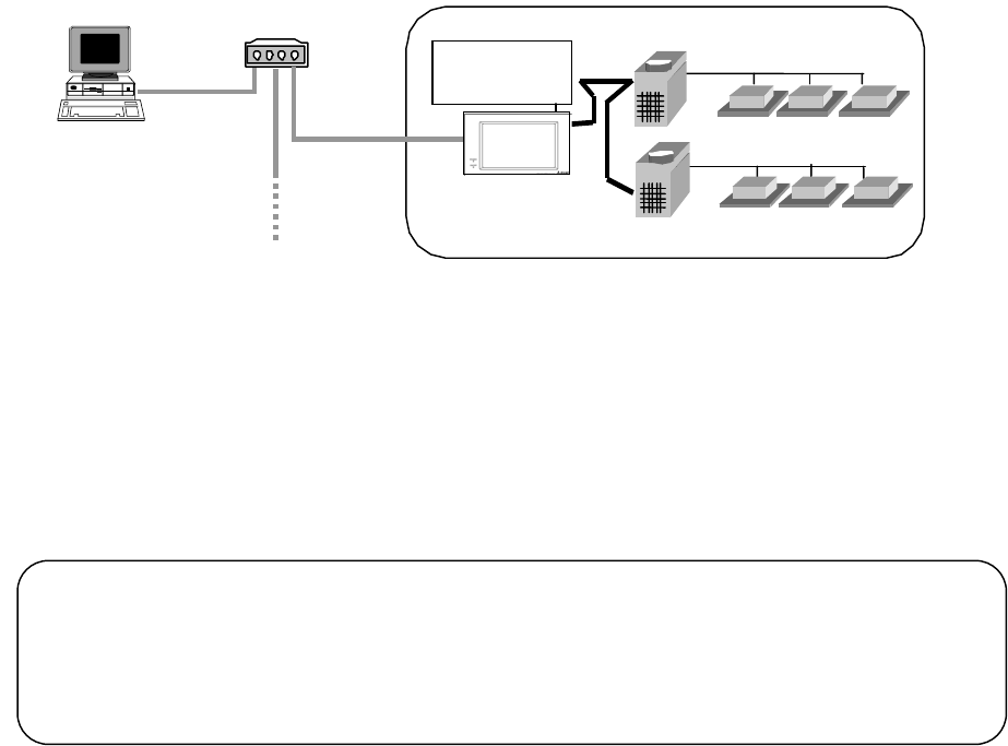
Power
supply unit
Step1
Integrated centralized
control software
TG - 2000A
HUB
A
G-150
A
or G-50A