


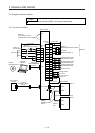
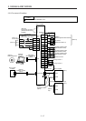
3. SIGNALS AND WIRING
3 - 19
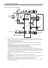
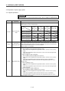
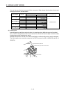
Symbol
Connection target
(application)
Description
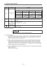
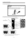
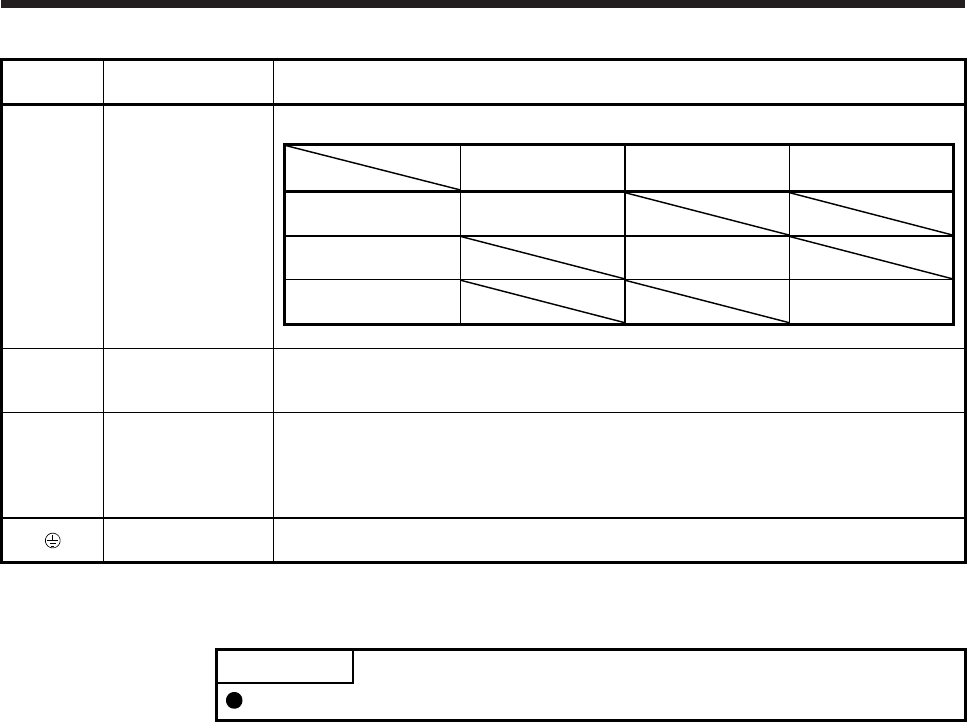
L11/L21
Control circuit power
supply
Supply the following power to L11 and L21.
Servo amplifier
Power
MR-J4-10B(-RJ) to
MR-J4-22KB(-RJ)
MR-J4-60B4(-RJ) to
MR-J4-22KB4(-RJ)
MR-J4-10B1 to
MR-J4-40B1
1-phase 200 V AC to
240 V AC, 50 Hz/60 Hz
L11/L21
1-phase 380 V AC to
480 V AC, 50 Hz/60 Hz
L11/L21
1-phase 100 V AC to
120 V AC, 50 Hz/60 Hz
L11/L21
U/V/W
Servo motor power
output
Connect the servo amplifier power output (U, V, and W) to the servo motor power input (U, V,
and W) directly. Do not let a magnetic contactor, etc. intervene. Otherwise, it may cause a
malfunction.
N-
Power regeneration
converter
Power regeneration
common converter
Brake unit
This terminal is used for a power regeneration converter, power regeneration common
converter and brake unit.
Refer to section 11.3 to 11.5 for details.
Protective earth (PE)
Connect it to the grounding terminal of the servo motor and to the protective earth (PE) of the
cabinet for grounding.
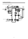
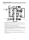
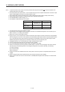
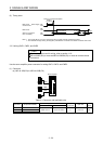
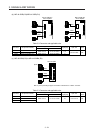
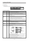
3.3.2 Power-on sequence
POINT
The output signal, etc. may be unstable at power-on.
(1) Power-on procedure
1) Always wire the power supply as shown in above section 3.1 using the magnetic contactor with
the main circuit power supply (L1/L2/L3). Configure up an external sequence to switch off the
magnetic contactor as soon as an alarm occurs.
2) Switch on the control circuit power supply (L11 and L21) simultaneously with the main circuit
power supply or before switching on the main circuit power supply. If the control circuit power
supply is turned on with the main circuit power supply off, and then the servo-on command is
transmitted, [AL. E9 Main circuit off warning] will occur. Turning on the main circuit power supply
stops the warning and starts the normal operation.
3) The servo amplifier receives the servo-on command within 3 s to 4 s after the main circuit power
supply is switched on.
(Refer to (2) of this section.)