


6. NORMAL GAIN ADJUSTMENT
6 - 15
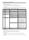
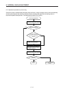
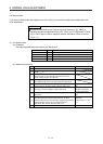
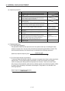
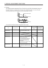
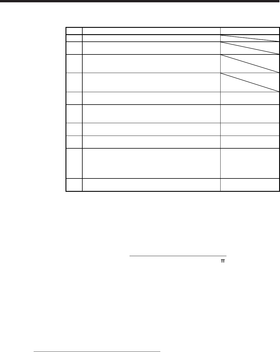
(b) Adjustment procedure
Step Operation Description
1 Brief-adjust with auto tuning. Refer to section 6.2.3.
2
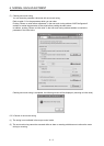
Change the setting of auto tuning to the manual mode ([Pr.
PA08]: _ _ _ 3).
3
Set the estimated value to the load to motor inertia ratio/load to
motor mass ratio. (If the estimate value with auto tuning is
correct, setting change is not required.)
4
Set a slightly smaller value to the model loop gain and the
position loop gain.
Set a slightly larger value to the speed integral compensation.
5
Increase the speed loop gain within the vibration- and unusual
noise-free range, and return slightly if vibration takes place.
Increase the speed loop
gain.
6
Decrease the speed integral compensation within the vibration-
free range, and return slightly if vibration takes place.
Decrease the time
constant of the speed
integral compensation.
7
Increase the position loop gain, and return slightly if vibration
takes place.
Increase the position loop
gain.
8
Increase the model loop gain, and return slightly if overshoot
takes place.
Increase the model loop
gain.
9
If the gains cannot be increased due to mechanical system
resonance or the like and the desired response cannot be
achieved, response may be increased by suppressing resonance
with the adaptive tuning mode or machine resonance
suppression filter and then executing steps 3 to 8.
Suppression of machine
resonance
Refer to section 7.2 and
7.3.
10
While checking the settling characteristic and motor status, fine-
adjust each gain.
Fine adjustment
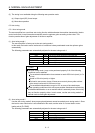
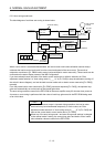
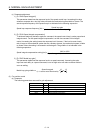
(c) Parameter adjustment
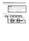
1) [Pr. PB09 Speed loop gain]
This parameter determines the response level of the speed control loop. Increasing this value
enhances response but a too high value will make the mechanical system liable to vibrate. The
actual response frequency of the speed loop is as indicated in the following expression.
Speed loop response frequency [Hz] =
(1 + Load to motor inertia ratio) × 2
Speed loop gain
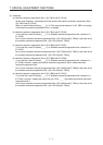
2) [Pr. PB10 Speed integral compensation]
To eliminate stationary deviation against a command, the speed control loop is under proportional
integral control. For the speed integral compensation, set the time constant of this integral
control. Increasing the setting lowers the response level. However, if the load to motor inertia
ratio is large or the mechanical system has any vibratory element, the mechanical system is liable
to vibrate unless the setting is increased to some degree. The guideline is as indicated in the
following expression.
Speed integral compensation setting [ms]
≥
2000 to 3000
Speed loop gain/(1 + Load to motor inertia ratio)