


4. STARTUP
4 - 3
4.1.2 Wiring check
(1) Power supply system wiring
Before switching on the main circuit and control circuit power supplies, check the following items.
(a) Power supply system wiring
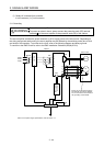
1) The power supplied to the power input terminals (L1, L2, L3, L11, and L21) of the servo amplifier
should satisfy the defined specifications. (Refer to section 1.3.)
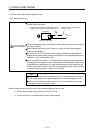
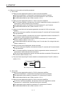
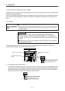
2) When the power factor improving DC reactor is not used, between P3 and P4 should be
connected.
P3
P4
Servo amplifie
r
(Note)
Note. The 100 V class servo amplifiers do not have P3 and P4.
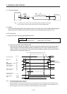
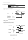
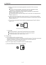
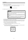
(b) Connection of servo amplifier and servo motor
1) The servo amplifier power output (U, V, and W) should match in phase with the servo motor
power input terminals (U, V, and W).
Servo amplifie
r
Servo moto
r
M
U
V
W
U
V
W
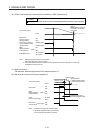
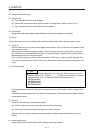
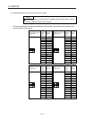
2) The power supplied to the servo amplifier should not be connected to the servo motor power
terminals (U, V, and W). To do so will fail the connected servo amplifier and servo motor.
Servo amplifier Servo motor
M
U
V
W
U
V
W
L1
L2
L3
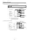
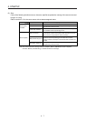
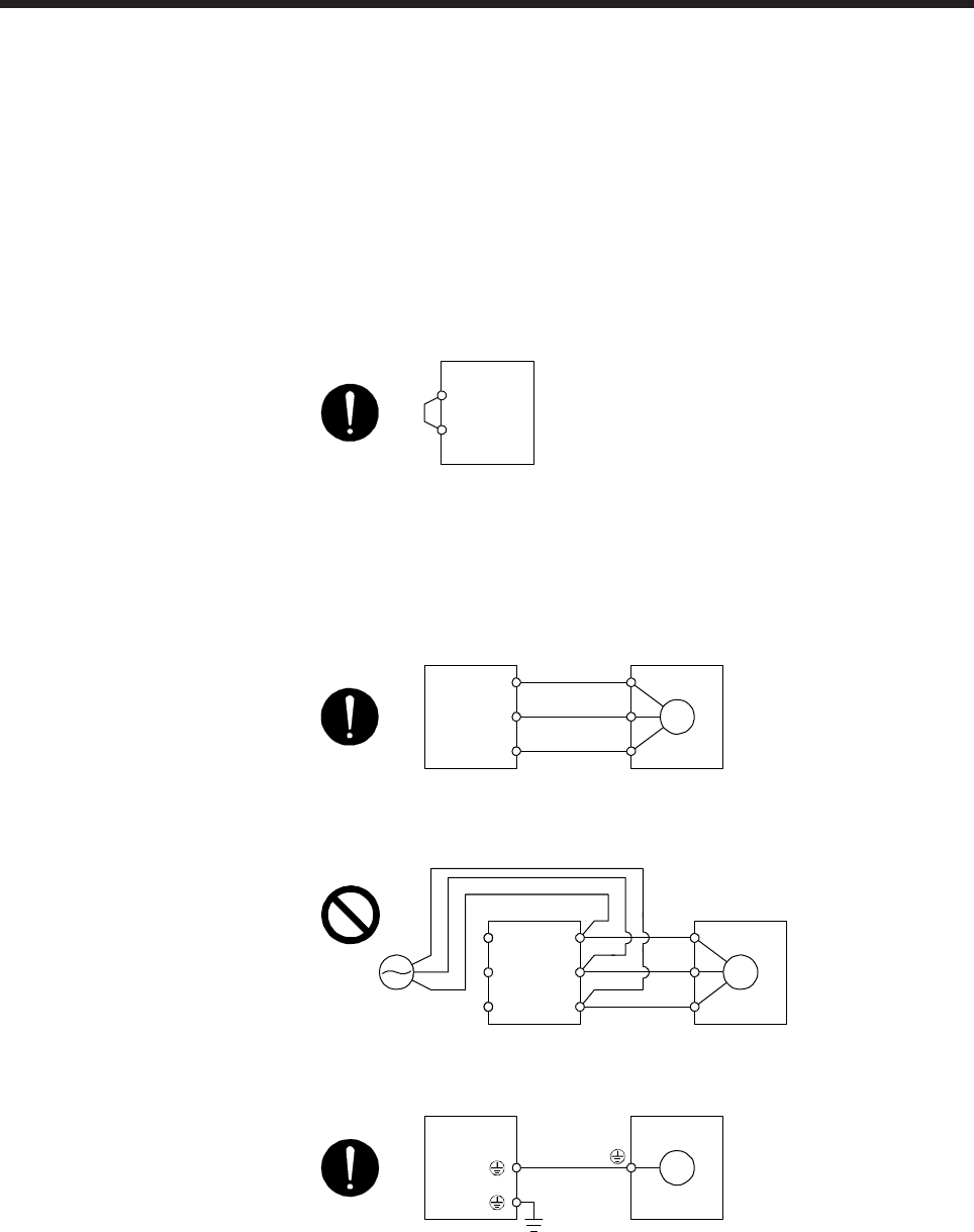
3) The grounding terminal of the servo motor is connected to the PE terminal of the servo amplifier.
Servo amplifier Servo motor
M
4) The CN2 connector of the servo amplifier should be connected to the encoder of the servo motor
securely using the encoder cable.