7. SPECIAL ADJUSTMENT FUNCTIONS
7 - 16
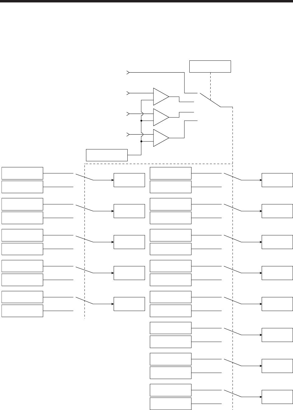
7.2.2 Function block diagram
The control gains, load to motor inertia ratio, and vibration suppression control settings are changed
according to the conditions selected by [Pr. PB26 Gain switching function] and [Pr. PB27 Gain switching
condition].
Command pulse
frequency
+
-
Droop pulses
Model speed
Control command
from controller
Comparator
Changing
CDP
[Pr. PB26]
+
-
+
-
GD2
[Pr. PB06]
GD2B
[Pr. PB29]
Enabled
GD2 value
PG1
[Pr. PB07]
PG1B
[Pr. PB60]
Enabled
PG1 value
PG2
[Pr. PB08]
PG2B
[Pr. PB30]
Enabled
PG2 value
VG2
[Pr. PB09]
VG2B
[Pr. PB31]
Enabled
VG2 value
VIC
[Pr. PB10]
VICB
[Pr. PB32]
Enabled
VIC value
VRF11
[Pr. PB19]
VRF11B
[Pr. PB33]
Enabled
VRF11 value
VRF12
[Pr. PB20]
VRF12B
[Pr. PB34]
Enabled
VRF12 value
CDL
[Pr. PB27]
VRF13
[Pr. PB21]
VRF13B
[Pr. PB35]
Enabled
VRF13 value
VRF14
[Pr. PB22]
VRF14B
[Pr. PB36]
Enabled
VRF14 value
VRF21
[Pr. PB52]
VRF21B
[Pr. PB56]
Enabled
VRF21 value
VRF22
[Pr. PB53]
VRF22B
[Pr. PB57]
Enabled
VRF22 value
VRF23
[Pr. PB54]
VRF23B
[Pr. PB58]
Enabled
VRF23 value
VRF24
[Pr. PB55]
VRF24B
[Pr. PB59]
Enabled
VRF24 value


