


3. SIGNALS AND WIRING
3 - 27
Device Symbol Function and application
Limiting torque TLC When the torque reaches the torque limit value during torque generation, TLC will turn on. When
the servo is off, TLC will be turned off.
This device cannot be used in the torque control mode.
Warning WNG When warning has occurred, WNG turns on. When a warning is not occurring, turning on the power
will turn off WNG after 2.5 s to 3.5 s.
Battery warning BWNG BWNG turns on when [AL. 92 Battery cable disconnection warning] or [AL. 9F Battery warning] has
occurred. When the battery warning is not occurring, turning on the power will turn off BWNG after
2.5 s to 3.5 s.
Variable gain
selection
CDPS CDPS will turn on during variable gain.
Absolute position
undetermined
ABSV ABSV turns on when the absolute position is undetermined.
The device cannot be used in the speed control mode and torque control mode.
During tough drive MTTR When a tough drive is enabled in [Pr. PA20], activating the instantaneous power failure tough drive
will turn on MTTR.
During fully closed
loop control
CLDS CLDS turns on during fully closed loop control.
3.5.3 Output signal
Signal name Symbol
Connector
pin No.
Function and application
Encoder A-phase
pulse (differential line
driver)
LA
LAR
CN3-6
CN3-16
These devices output pulses of encoder output set in [Pr. PA15] and [Pr. PA16] in the
differential line driver type.
In CCW rotation of the servo motor, the encoder B-phase pulse lags the encoder A-
phase pulse by a phase angle of π/2.
The relation between rotation direction and phase difference of the A-phase and B-
phase pulses can be changed with [Pr. PC03].
Output pulse specification, dividing ratio setting, and electronic gear setting can be
selected.
Encoder B-phase
pulse (differential line
driver)
LB
LBR
CN3-7
CN3-17
Encoder Z-phase
pulse (differential line
driver)
LZ
LZR
CN3-8
CN3-18
The encoder zero-point signal is output in the differential line driver type. One pulse is
output per servo motor revolution. This turns on when the zero-point position is
reached. (negative logic)
The minimum pulse width is about 400 μs. For home position return using this pulse,
set the creep speed to 100 r/min. or less.
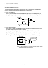
Analog monitor 1 MO1 CN3-4 This is used to output the data set in [Pr. PC09] to between MO1 and LG in terms of
voltage.
Resolution: 10 bits or equivalent
Analog monitor 2 MO2 CN3-14 This signal output the data set in [Pr. PC10] to between MO2 and LG in terms of
voltage.
Resolution: 10 bits or equivalent
3.5.4 Power supply
Signal name Symbol
Connector
pin No.
Function and application
Digital I/F power
supply input
DICOM CN3-5
CN3-10
Input 24 V DC (24 V DC ± 10% 300 mA) for I/O interface. The power supply capacity
changes depending on the number of I/O interface points to be used.
For sink interface, connect + of 24 V DC external power supply.
For source interface, connect - of 24 V DC external power supply.
Digital I/F common DOCOM CN3-3 Common terminal of input signal such as EM2 of the servo amplifier. This is separated
from LG.
For sink interface, connect - of 24 V DC external power supply.
For source interface, connect + of 24 V DC external power supply.
Monitor common LG CN3-1
CN3-11
Common terminal of MO1 and MO2.
Pins are connected internally.
Shield SD Plate Connect the external conductor of the shielded wire.