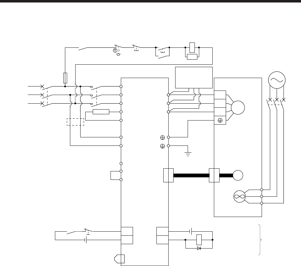
3. SIGNALS AND WIRING
3 - 8
(5) MR-J4-11KB(-RJ)/MR-J4-15KB(-RJ)/MR-J4-22KB(-RJ)
C
P+
L11
L21
P3
P4
N-
L1
L2
L3
U
V
W
U
V
W
M
CN2
MC
MC
SK
CN8
MCCB
BU
BV
BW
MCCB
ALM
DOCOM
CN3
RA1
CN3
EM2
DICOM
MC
(Note 7)
(Note 5)
24 V DC (Note 12)
Malfunction (Note 4)
3-phase
200 V AC to
240 V AC
Servo amplifier
(Note 1)
(Note 10)
(Note 2)
Servo motor
Motor
Encoder
(Note 3)
Encoder
cable
(Note 6)
(Note 4)
Malfunction
RA1
OFF
ON
EMG stop switch
(Note 5) Forced stop 2
(Note 9)
Short-circuit connector
(Packed with the servo amplifier)
(Note 8)
Main circuit power supply
(Note 11)
(Note 11)
24 V DC (Note 12)
(Note 15, 16)
External
dynamic
brake (optional)
(Note 14)
Cooling fan
power supply
Cooling fan
(Note 13)


