


11. OPTIONS AND PERIPHERAL EQUIPMENT
11 - 76
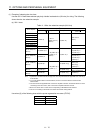
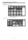
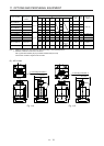
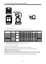
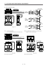
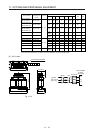
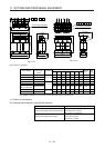
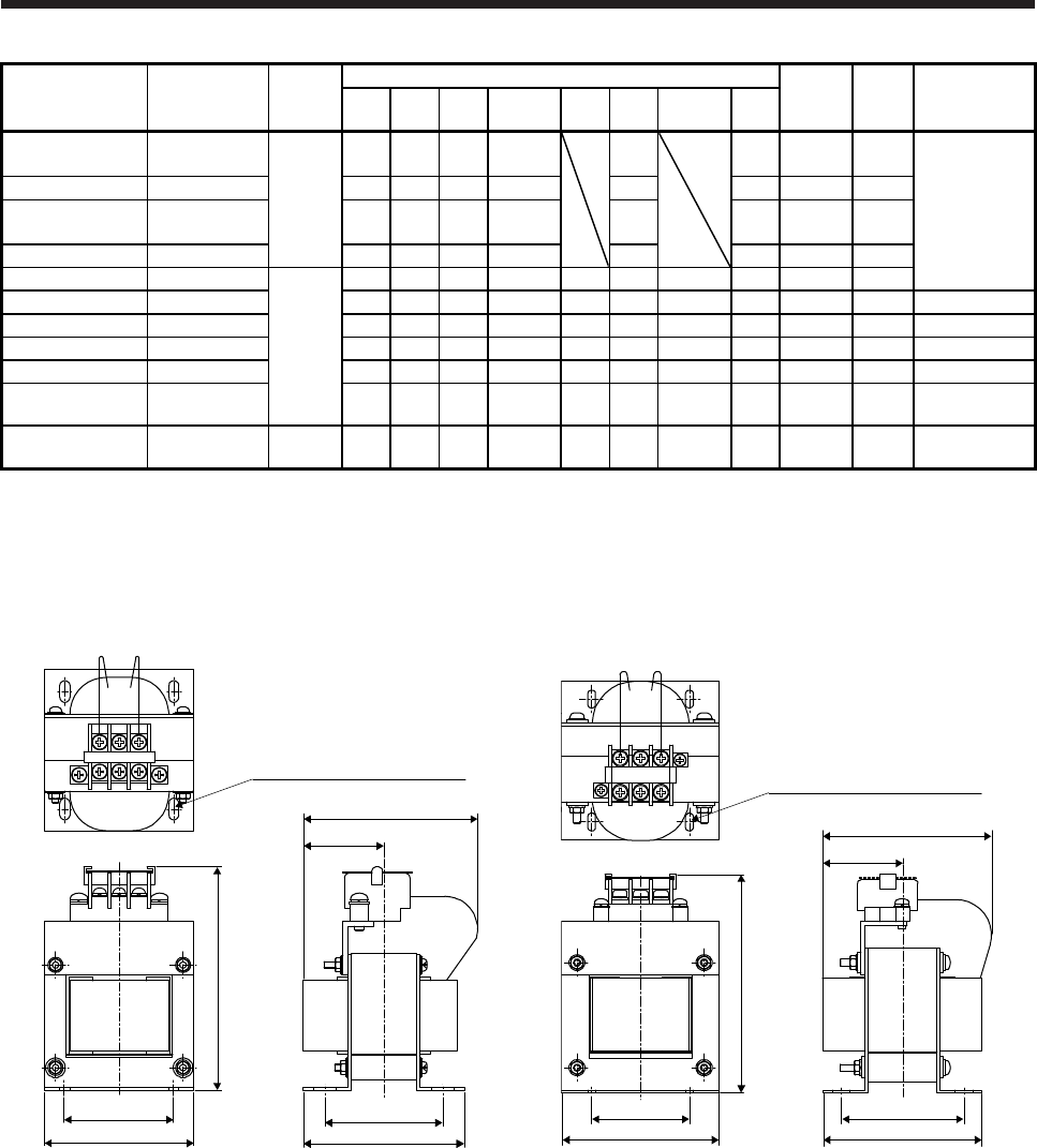
Servo amplifier
Power factor
improving DC
reactor
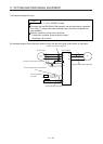
Dimensions
Dimensions [mm]
Terminal
size
Mass
[kg]
Wire [mm
2
]
(Note 2)
W W1 H
D
(Note 1)
D1 D2 D3 d
MR-J4-10B(-RJ)
MR-J4-20B(-RJ)
FR-HEL-0.4K
Fig. 11.1
70 60 71 61
21
M4 M4 0.4
2 (AWG 14)
MR-J4-40B(-RJ) FR-HEL-0.75K 85 74 81 61 21 M4 M4 0.5
MR-J4-60B(-RJ)
MR-J4-70B(-RJ)
FR-HEL-1.5K 85 74 81 70 30 M4 M4 0.8
MR-J4-100B(-RJ) FR-HEL-2.2K 85 74 81 70 30 M4 M4 0.9
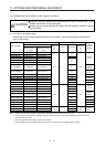
MR-J4-200B(-RJ) FR-HEL-3.7K
Fig. 11.2
77 55 92 82 66 57 37 M4 M4 1.5
MR-J4-350B(-RJ) FR-HEL-7.5K 86 60 113 98 81 72 43 M4 M5 2.5 3.5 (AWG 12)
MR-J4-500B(-RJ) FR-HEL-11K 105 64 133 112 92 79 47 M6 M6 3.3 5.5 (AWG 10)
MR-J4-700B(-RJ) FR-HEL-15K 105 64 133 115 97 84 48.5 M6 M6 4.1 8 (AWG 8)
MR-J4-11KB(-RJ) FR-HEL-15K 105 64 133 115 97 84 48.5 M6 M6 4.1 14 (AWG 6)
MR-J4-15KB(-RJ) FR-HEL-22K 105 64 93 175 117 104
115
(Note 1)
M6 M10 5.6 22 (AWG 4)
MR-J4-22KB(-RJ) FR-HEL-30K Fig. 11.3 114 72 100 200 125 101
135
(Note 1)
M6 M10 7.8 38 (AWG 2)
Note 1. Maximum dimensions The dimension varies depending on the input/output lines.
2. Selection conditions of wire size is as follows.
600 V grade heat-resistant polyvinyl chloride insulated wire (HIV wire)
Construction condition: Single wire set in midair
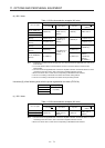
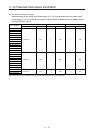
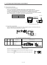
(2) 400 V class
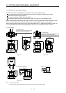
W1
D2
W ± 2.5
H ± 2.5
D or less
(D3)
D1 ± 1
4-d mounting hole (Note 1)
PP1
Fig. 11.4
W1
W ± 2.5
D2
D1 ± 1
H ± 2.5
PP1
D or less
(D3)
4-d mounting hole (Note 1)
Fig. 11.5