


APPENDIX
App. - 32
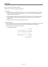
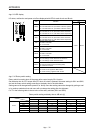
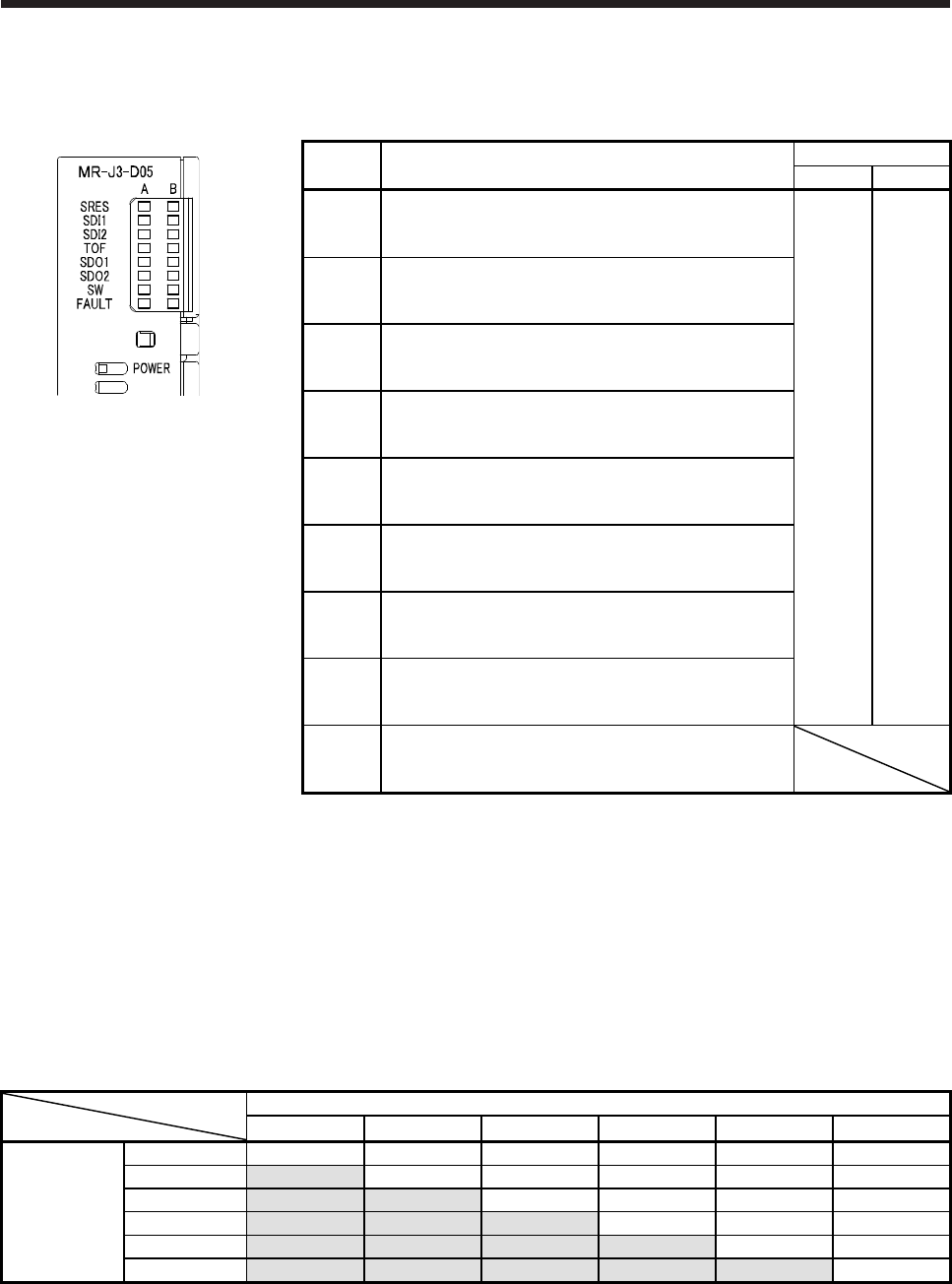
App. 5.9 LED display
I/O status, malfunction and power on/off are displayed with LED for each A-axis and B-axis.
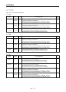
LED Definition
LED
Column A Column B
SRES
Monitor LED for start/reset
Off: The start/reset is off. (The switch contact is opened.)
On: The start/reset is on. (The switch contact is closed.)
A-axis B-axis
SDI1
Monitor LED for shut-off 1
Off: The shut-off 1 is off. (The switch contact is closed.)
On: The shut-off 1 is on. (The switch contact is opened.)
SDI2
Monitor LED for shut-off 2
Off: The shut-off 2 is off. (The switch contact is closed.)
On: The shut-off 2 is on. (The switch contact is opened.)
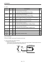
TOF
Monitor LED for STO state
Off: Not in STO state
On: In STO state
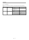
SDO1
Monitor LED for SDO1
Off: Not in STO state
On: In STO state
SDO2
Monitor LED for SDO2
Off: Not in STO state
On: In STO state
SW
Monitor LED for confirming shutdown delay setting
Off: The settings of SW1 and SW2 do not match.
On: The settings of SW1 and SW2 match.
FAULT
FAULT LED
Off: Normal operation (STO monitoring state)
On: Fault has occurred.
POWER
Power
Off: Power is not supplied to MR-J3-D05.
On: Power is being supplied to MR-J3-D05.
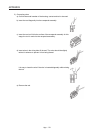
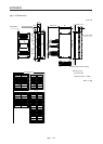
App. 5.10 Rotary switch setting
Rotary switch is used to shut off the power after control stop by SS1 function.
Set the delay time for STO output after STO shut off switch is pressed. Set same setting for SW1 and SW2,
and set the rotary switch setting according to the delay time in the table below.
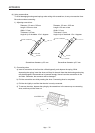
Setting cannot be changed while power is on. Notify users that setting cannot be changed by putting a seal
or by another method so that end users will not change the setting after the shipment.
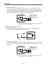
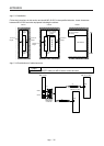
0 to F in the following table is the set value of the rotary switches (SW1 and SW2).
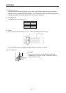
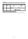
Rotary switch setting and delay time at A/B-axis [s]
B-axis
0 s 1.4 s 2.8 s 5.6 s 9.8 s 30.8 s
0 s 0 1 2 - 3 4
1.4 s - 5 - 6 7
A-axis
2.8 s
8 - 9 A
5.6 s - B C
9.8 s D E
30.8 s F