


5. PARAMETERS
5 - 23
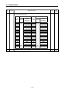
No. Symbol Name and function
Initial
value
[unit]
Setting
range
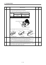
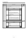
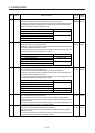
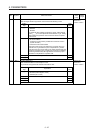
PB06 GD2 Load to motor inertia ratio/load to motor mass ratio
This is used to set the load to motor inertia ratio or load to motor mass ratio.
The setting of the parameter will be the automatic setting or manual setting depending on the
[Pr. PA08] setting. Refer to the following table for details. When the parameter is automatic
setting, the value will vary between 0.00 and 100.00.
7.00
Multiplier
0.00 to
300.00
Pr. PA08 This parameter
_ _ _ 0 (2 gain adjustment mode 1 (interpolation mode)) Automatic setting
_ _ _ 1 (Auto tuning mode 1)
_ _ _ 2 (Auto tuning mode 2) Manual setting
_ _ _ 3 (Manual mode)
_ _ _ 4 (2 gain adjustment mode 2)
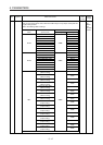
PB07 PG1 Model loop gain
Set the response gain up to the target position.
Increasing the setting value will also increase the response level to the position command but
will be liable to generate vibration and/or noise.
The setting of the parameter will be the automatic setting or manual setting depending on the
[Pr. PA08] setting. Refer to the following table for details.
15.0
[rad/s]
1.0 to
2000.0
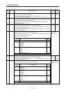
Pr. PA08 This parameter
_ _ _ 0 (2 gain adjustment mode 1 (interpolation mode)) Manual setting
_ _ _ 1 (Auto tuning mode 1) Automatic setting
_ _ _ 2 (Auto tuning mode 2)
_ _ _ 3 (Manual mode) Manual setting
_ _ _ 4 (2 gain adjustment mode 2)
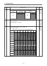
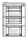
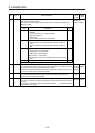
PB08 PG2 Position loop gain
This is used to set the gain of the position loop.
Set this parameter to increase the position response to level load disturbance.
Increasing the setting value will also increase the response level to the load disturbance but
will be liable to generate vibration and/or noise.
The setting of the parameter will be the automatic setting or manual setting depending on the
[Pr. PA08] setting. Refer to the following table for details.
37.0
[rad/s]
1.0 to
2000.0
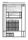
Pr. PA08 This parameter
_ _ _ 0 (2 gain adjustment mode 1 (interpolation mode)) Automatic setting
_ _ _ 1 (Auto tuning mode 1)
_ _ _ 2 (Auto tuning mode 2)
_ _ _ 3 (Manual mode) Manual setting
_ _ _ 4 (2 gain adjustment mode 2) Automatic setting
PB09 VG2 Speed loop gain
This is used to set the gain of the speed loop.
Set this parameter when vibration occurs on machines of low rigidity or large backlash.
Increasing the setting value will also increase the response level but will be liable to generate
vibration and/or noise.
The setting of the parameter will be the automatic setting or manual setting depending on the
[Pr. PA08] setting. Refer to the table of [Pr. PB08] for details.
823
[rad/s]
20 to
65535
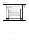
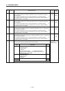
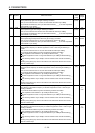
PB10 VIC Speed integral compensation
This is used to set the integral time constant of the speed loop.
Decreasing the setting value will increase the response level but will be liable to generate
vibration and/or noise.
The setting of the parameter will be the automatic setting or manual setting depending on the
[Pr. PA08] setting. Refer to the table of [Pr. PB08] for details.
33.7
[ms]
0.1 to
1000.0