


14. USING A LINEAR SERVO MOTOR
14 - 2
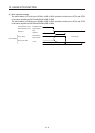
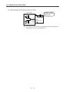
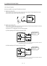
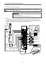
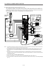
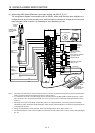
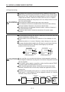
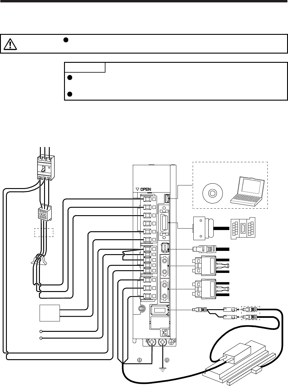
14.1.2 Servo system with auxiliary equipment
CAUTION
Connecting a linear servo motor for different axis to the U, V, W, or CN2 may
cause a malfunction.
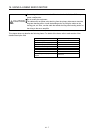
POINT
Equipment other than the servo amplifier and linear servo motor are optional or
recommended products.
When using the linear servo motor, set [Pr. PA01] to "_ _ 4 _".
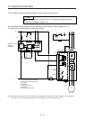
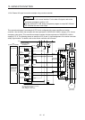
(1) MR-J4-_B_
The configuration diagram is an example of MR-J4-20B. When using the other servo amplifiers, the
configuration will be the same as rotary servo motors except for connections of linear servo motors and
linear encoders. Refer to section 1.8 depending on servo amplifiers you use.
Line noise
filter
(FR-BSF01)
CN5
Regenerative
option
P+
C
L11
L21
P3
P4
Personal
computer
MR Configurator2
CN3
CN8
CN1A
CN1B
CN2
W
V
U
L1
L2
L3
(Note 3)
Magnetic
contactor
(MC)
(Note 1)
Power factor
improving DC
reactor
(FR-HEL)
Molded-case
circuit breaker
(MCCB)
Junction
terminal
block
Safety relay or
MR-J3-D05 safety
logic unit
Servo system controller
or previous servo
amplifier CN1B
Next servo amplifier
CN1A or cap
(Note 2)
Power
supply
RST
(Note 4)
Linear encoder
Linear servo motor
Encoder
cable
SCALE
THM
D
(Note 5)
(Note 6)
Thermistor