


3. SIGNALS AND WIRING
3 - 28
3.6 Forced stop deceleration function
POINT
When alarms not related to the forced stop function occur, control of motor
deceleration can not be guaranteed. (Refer to chapter 8.)
When SSCNET III/H communication brake occurs, forced stop deceleration will
operate. (Refer to section 3.7.1 (3).)
In the torque control mode, the forced stop deceleration function is not available.
3.6.1 Forced stop deceleration function
When EM2 is turned off, dynamic brake will start to stop the servo motor after forced stop deceleration.
During this sequence, the display shows [AL. E6 Servo forced stop warning].
During normal operation, do not use EM2 (Forced stop 2) to alternate stop and drive. The the servo amplifier
life may be shortened.
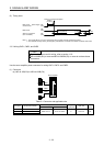
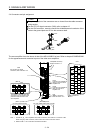
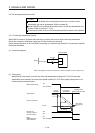
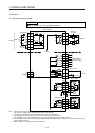
(1) Connection diagram
Servo amplifier
Forced stop 2
DICOM
EM2
24 V DC
(Note)
Note. This diagram is for sink I/O interface. For source I/O interface, refer to section 3.8.3.
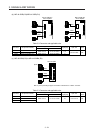
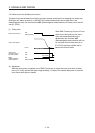
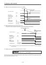
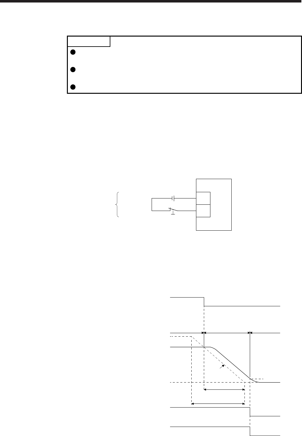
(2) Timing chart
When EM2 (Forced stop 2) turns off, the motor will decelerate according to [Pr. PC24 Forced stop
deceleration time constant]. Once the motor speed is below [Pr. PC07 Zero speed], base power is cut
and the dynamic brake activates.
Base circuit
(Energy supply to
t
he servo motor)
0 r/min
Servo motor speed
MBR
(Electromagneti
c
brake interlock)
ON
OFF (Enabled)
ON
OFF
Deceleration time
Command
Rated Speed
Ordinary
operation
Forced stop
deceleration
Dynamic brake
+
Electromagnetic brake
ON
OFF (Enabled)
EM2 (Forced stop 2)
Zero speed
([Pr. PC07])
[Pr. PC24]