


1. FUNCTIONS AND CONFIGURATION
1 - 22
Function Description
Detailed
explanation
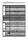
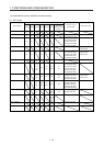
Fully closed loop system
Fully closed loop system can be configured using the load-side encoder.
This is used with servo amplifiers with software version A3 or later. Check the
software version of the servo amplifier using MR Configurator2.
Chapter 16
One-touch tuning
Gain adjustment is performed just by one click on a certain button on MR
Configurator2.
MR Configurator2 is necessary for this function.
Section 6.2
SEMI-F47 function (Note)
Enables to avoid triggering [AL. 10 Undervoltage] using the electrical energy charged
in the capacitor in case that an instantaneous power failure occurs during operation.
Use a 3-phase for the input power supply of the servo amplifier. Using a 1-phase 100
V AC/200 V AC for the input power supply will not comply with SEMI-F47 standard.
[Pr. PA20]
[Pr. PF25]
Section 7.4
Tough drive function
This function makes the equipment continue operating even under the condition that
an alarm occurs.
The tough drive function includes two types: the vibration tough drive and the
instantaneous power failure tough drive.
Section 7.3
Drive recorder function
This function continuously monitors the servo status and records the status transition
before and after an alarm for a fixed period of time. You can check the recorded data
on the drive recorder window on MR Configurator2 by clicking the "Graph" button.
However, the drive recorder will not operate on the following conditions.
1. You are using the graph function of MR Configurator2.
2. You are using the machine analyzer function.
3. [Pr. PF21] is set to "-1".
4. The controller is not connected (except the test operation mode).
5. An alarm related to the controller is occurring.
[Pr. PA23]
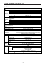
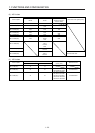
STO function
This function is a functional safety that complies with IEC/EN 61800-5-2. You can
create a safety system for the equipment easily.
Servo amplifier life diagnosis
function
You can check the cumulative energization time and the number of on/off times of the
inrush relay. This function gives an indication of the replacement time for parts of the
servo amplifier including a capacitor and a relay before they malfunction.
MR Configurator2 is necessary for this function.
Power monitoring function
This function calculates the power running energy and the regenerative power from
the data in the servo amplifier such as speed and current. For the SSCNET III/H
system, MR Configurator2 can display the data, including the power consumption.
Since the servo amplifier can send the data to a servo system controller, you can
analyze the data and display the data on a display.
Machine diagnosis function
From the data in the servo amplifier, this function estimates the friction and vibrational
component of the drive system in the equipment and recognizes an error in the
machine parts, including a ball screw and bearing.
MR Configurator2 is necessary for this function.
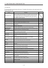
Master-slave operation
function
The function transmits a master axis torque to slave axes using driver communication
and the torque as a command drives slave axes by torque control.
This is used with servo amplifiers with software version A8 or later. Check the
software version of the servo amplifier using MR Configurator2.
Section 17.2
Scale measurement function
The function transmits position information of a scale measurement encoder to the
controller by connecting the scale measurement encoder in semi closed loop control.
This is used with servo amplifiers with software version A8 or later. Check the
software version of the servo amplifier using MR Configurator2.
Section 17.3
J3 compatibility mode
This amplifier has "J3 compatibility mode" which compatible with the previous MR-J3-
B series. Refer to section 17.1 for software versions.
Section 17.1
Continuous operation to
torque control mode
This enables to smoothly switch the mode from position control mode/speed control
mode to torque control mode without stopping. This also enables to decrease load to
the machine and high quality molding without rapid changes in speed or torque. For
details of the continuous operation to torque control mode, refer to the manuals for
servo system controllers.
[Pr. PB03]
Refer to the
servo system
controller
manual used.
Lost motion compensation
function
This function improves the response delay occurred when the machine moving
direction is reversed. This is used with servo amplifiers with software version B4 or
later. Check the software version of the servo amplifier using MR Configurator2.
Section 7.6
Super trace control
This function sets constant and uniform acceleration/deceleration droop pulses to
almost 0. This is used with servo amplifiers with software version B4 or later. Check
the software version of the servo amplifier using MR Configurator2.
Section 7.7
Note. For servo system controllers which are available with this, contact your local sales office.