


14. USING A LINEAR SERVO MOTOR
14 - 26
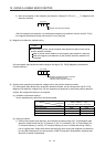
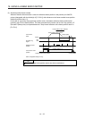
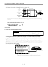
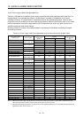
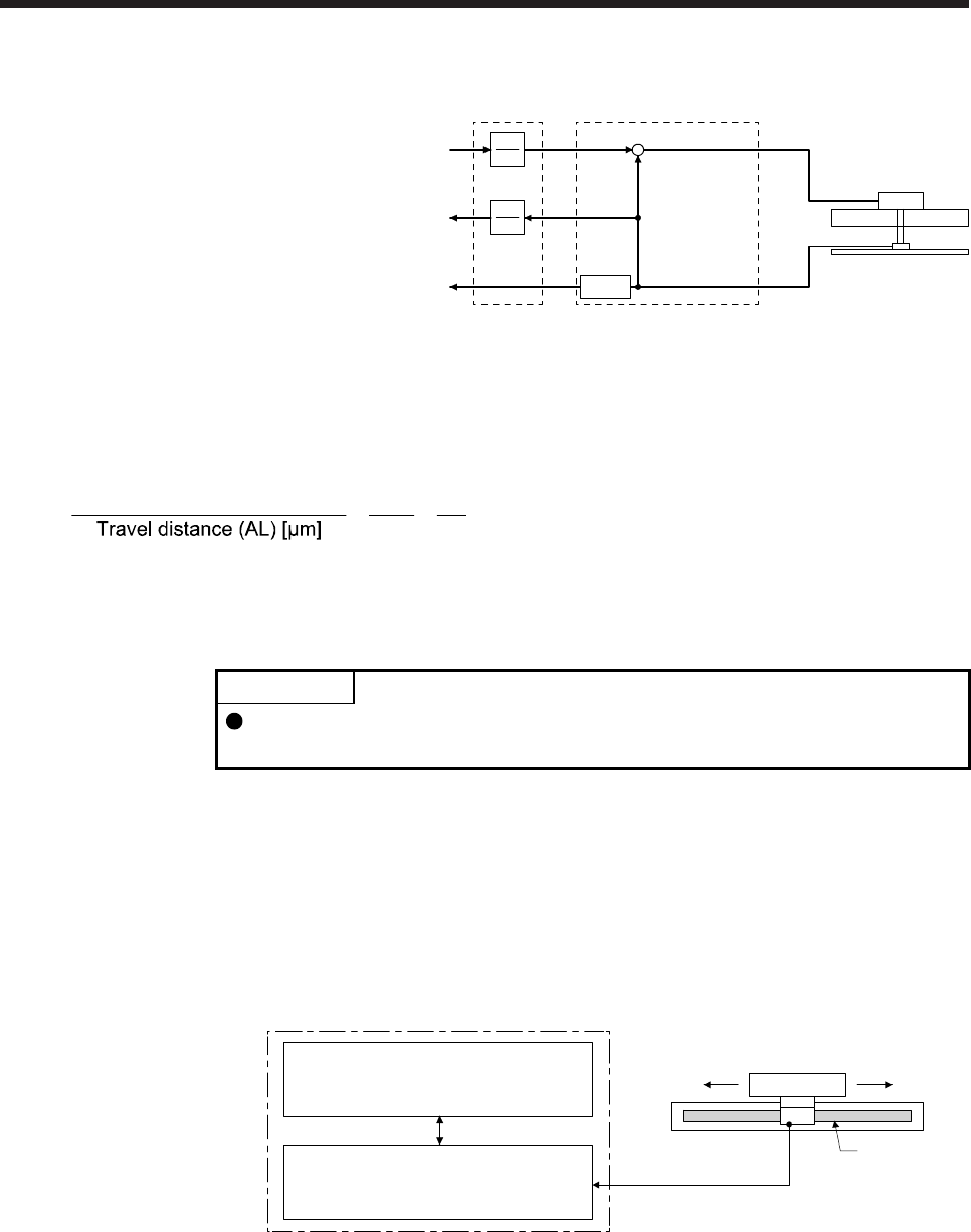
(b) Settings of the number of pulses (AP) and travel distance (AL)
AP
AL
Position feedback
[mm]
Command
[mm]
+
-
Speed feedback
[mm/s]
AL
AP
User
Controlle
r
Servo amplifie
r
Linear servo
motor
Linear encoder
Differ-
entiation
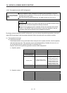
Calculate the number of pulses (AP) and travel distance (AL) of the linear encoder in the following
conditions.
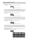
When the linear encoder resolution is 0.05 µm
Number of pulses (AP) [pulse]
=
1
0.05
=
20
1
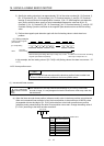
14.3.6 Function
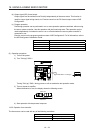
(1) Linear servo control error detection function
POINT
For the linear servo control error detection function, the position and speed
deviation error detections are enabled by default. ([Pr. PL04]: _ _ _ 3)
If the linear servo control gets unstable for some reasons, the linear servo motor may not operate
properly. To detect this state and to stop operation, the linear servo control error detection function is
used as a protective function.
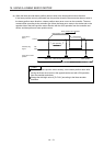
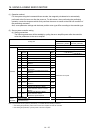
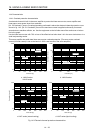
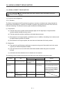
The linear servo control error detection function has three different detection methods: the position
deviation, speed deviation, and thrust deviation. An error is detected when each method is enabled with
[Pr. PL04 Linear servo motor/DD motor function selection 2]. The detection level can be changed with
[Pr. PL05], [Pr. PL06], and [Pr. PL07].
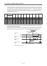
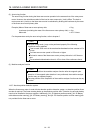
Servo amplifier internal value
1) Model feedback position [mm]
3) Model feedback speed [mm/s]
5) Command thrust [%]
Linear encoder
2) Feedback position [mm]
4) Feedback speed [mm/s]
6) Feedback thrust [%]
Servo amplifier
Linear servo motor
Linear encode
r
Figure 14.1 Outline of linear servo control error detection function