


17. APPLICATION OF FUNCTIONS
17 - 53
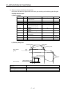
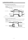
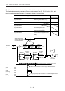
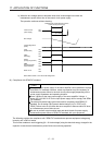
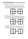
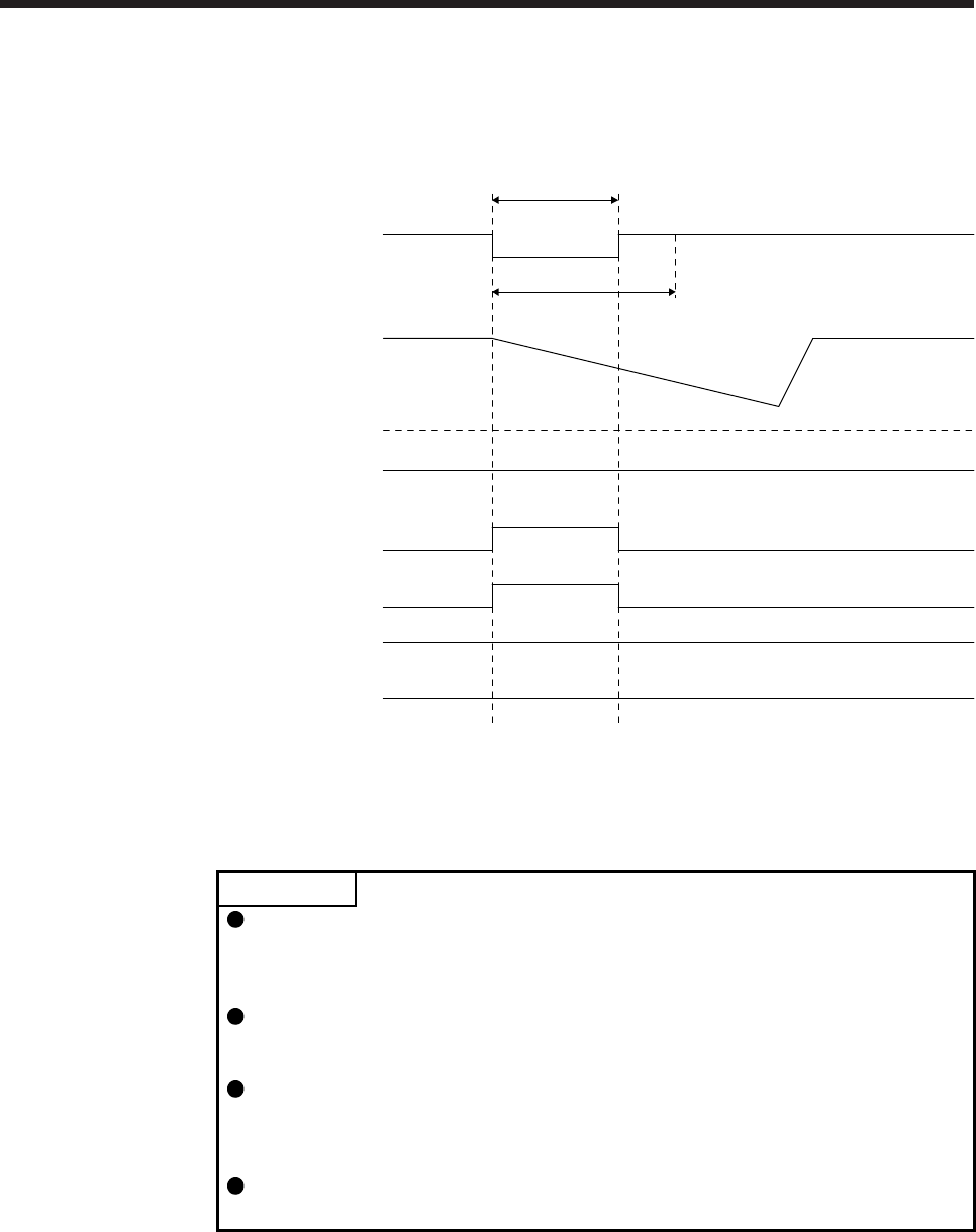
b) When the bus voltage does not decrease lower than Undervoltage level within the
instantaneous power failure time of the control circuit power supply
The operation continues without alarming.
Control circuit
power supply
Bus voltage
Undervoltage level
(Note)
A
LM
(Malfunction)
MTTR
(During tough drive)
MBR
(Electromagnetic
brake interlock)
Base circuit
WNG
(Warning)
[Pr. PX28]
Instantaneous power failure time of th
e
control circuit power supply
ON
OFF
ON
OFF
ON
OFF
ON
OFF
ON
OFF
ON
OFF
Note. Refer to table 17.6 for the undervoltage level.
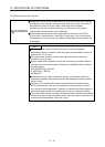
(8) Compliance with SEMI-F47 standard
POINT
The control circuit power supply of the servo amplifier can be possible to comply
with SEMI-F47 standard. However, a back-up capacitor may be necessary for
instantaneous power failure in the main circuit power supply depending on the
power supply impedance and operating situation.
Use a 3-phase for the input power supply of the servo amplifier. Using a 1-
phase 100 V AC/200 V AC for the input power supply will not comply with SEMI-
F47 standard.
The external dynamic brake cannot be used for compliance with SEMI-F47
standard. Do not assign DB (Dynamic brake interlock) in [Pr. PD07] to [Pr.
PD09]. Failure to do so will cause the servo amplifier to become servo-off when
an instantaneous power failure occurs.
Be sure to perform actual machine tests and detail checks for power supply
instantaneous power failure of SEMI-F47 standard with your equipment.
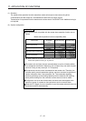
The following explains the compliance with "SEMI-F47 semiconductor process equipment voltage sag
immunity test" of MR-J4 series.
This function enables to avoid triggering [AL. 10 Undervoltage] using the electrical energy charged in the
capacitor in case that an instantaneous power failure occurs during operation.