


4. STARTUP
4 - 5
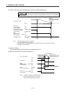
c) When you use a brake unit and power regeneration converter for 5 kW or more servo
amplifiers
For 5 kW or 7 kW servo amplifiers, the lead wire of the built-in regenerative resistor
connected to P+ terminal and C terminal should not be connected.
Brake unit, power regeneration converter should be connected to P+ terminal and N-
terminal. (Refer to section 11.3 to 11.4.)
A twisted cable should be used when wiring is over 5 m and under 10 m using a brake unit.
(Refer to section 11.3)
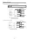
d) When you use a power regeneration common converter for 11 kW or more servo amplifiers
Power regeneration common converter should be connected to P4 terminal and N- terminal.
(Refer to section 11.5.)
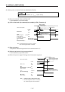
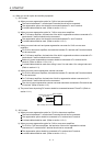
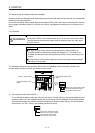
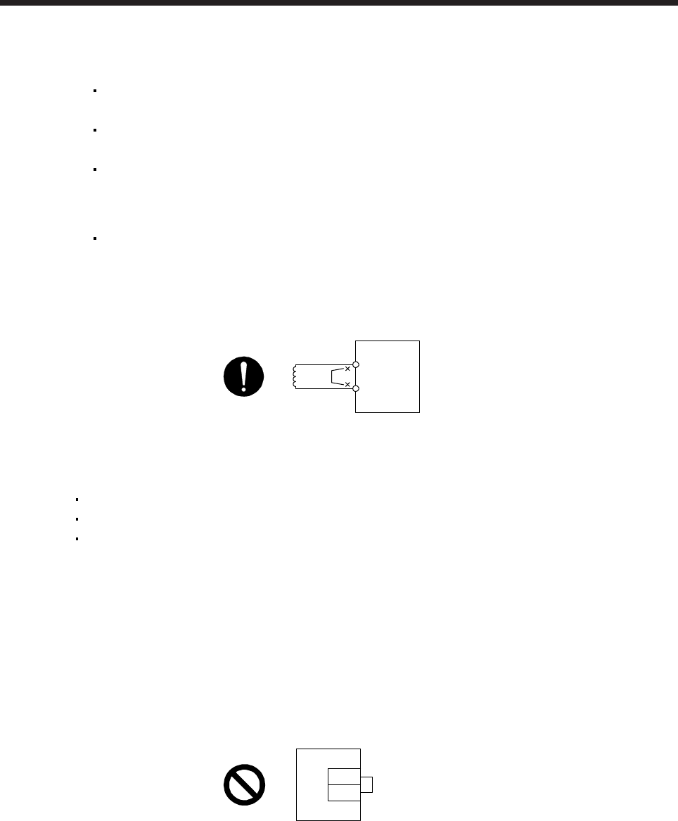
e) The power factor improving DC reactor should be connected between P3 and P4. (Refer to
section 11.11.)
(Note)
Power factor improving
DC reactor
Servo amplifie
r
P3
P4
Note.
A
lways disconnect between P3 and P4.
3) 100 V class
The lead wire between P+ terminal and D terminal should not be connected.
The regenerative option should be connected to P+ terminal and C terminal.
A twisted cable should be used. (Refer to section 11.2.4.)
(2) I/O signal wiring
(a) The I/O signals should be connected correctly.
Use DO forced output to forcibly turn on/off the pins of the CN3 connector. This function can be used
to perform a wiring check. In this case, switch on the control circuit power supply only.
Refer to section 3.2 for details of I/O signal connection.
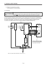
(b) 24 V DC or higher voltage is not applied to the pins of the CN3 connector.
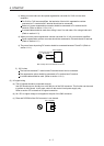
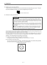
(c) Plate and DOCOM of the CN3 connector is not shorted.
Servo amplifier
DOCOM
Plate
CN3