


3. SIGNALS AND WIRING
3 - 15
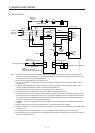
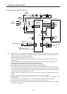
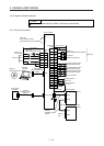
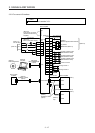
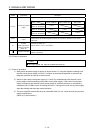
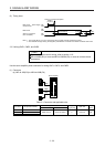
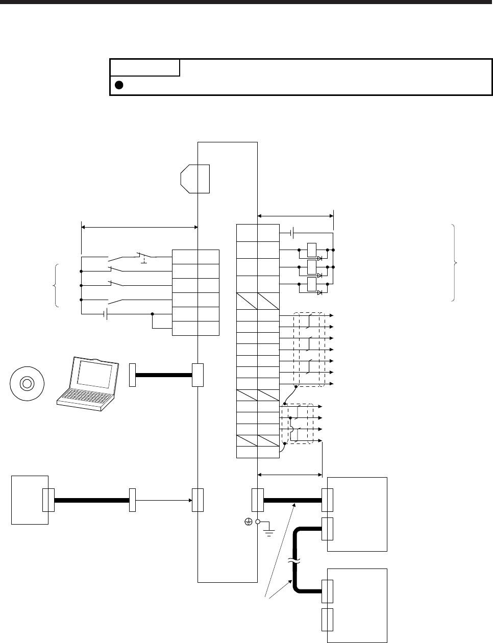
3.2 I/O signal connection example
POINT
EM2 has the same function as EM1 in the torque control mode.
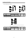
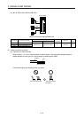
3.2.1 For sink I/O interface
20EM2
2
19
12
DI1
DI3
DI2
(Note 12)
(Note 2)
Servo amplifier
CN3
(Note 12)
(Note 14)
FLS
RLS
DOG
(Note 13)
Encoder A-phase pulse
(differential line driver)
Encoder B-phase pulse
(differential line driver)
Encoder Z-phase pulse
(differential line driver)
CN3
(Note 17)
Electromagnetic brake interlock
13 MBR
9 INP
15 ALM
6LA
16 LAR
7LB
17 LBR
8LZ
18 LZR
Malfunction (Note 11)
In-position
11 LG Control common
RA1
RA2
RA3
DOCOM
DICOM
3
10
5
DICOM
(Note 15)
Main circuit power supply
Personal
computer
CN5
(Note 5)
MR Configurator2
+
USB cable
MR-J3USBCBL3M
(option)
(Note 10) 24 V DC
Analog monitor 1
Analog monitor 2
MO1
LG
MO2
4
1
14
SDPlate
2 m or less
CN8
(Note 16)
Short-circuit connector
(Packed with the servo amplifier)
10 m or less
10 m or less
Servo amplifier
(Note 3, 4)
Forced stop 2
(Note 6)
SSCNET III cable
(option)
Servo system
controller
CN1A
CN1B
(Note 7)
(Note 1)
(Note 9)
Cap
CN1A
CN1B
The last servo amplifier (Note 8)
CN1BCN1A
(Note 6)
SSCNET III cable
(option)
(Note 7)
24 V DC (Note 10)
DC ± 10 V
DC ± 10 V