


1. FUNCTIONS AND CONFIGURATION
1 - 21
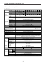
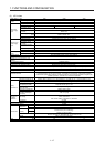
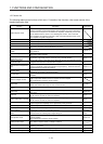
1.5 Function list
The following table lists the functions of this servo. For details of the functions, refer to each section of the
detailed description field.
Function Description
Detailed
explanation
Model adaptive control
This realizes a high response and stable control following the ideal model. The two-
degrees-of-freedom-model model adaptive control enables you to set a response to
the command and response to the disturbance separately. Additionally, this function
can be disabled. Refer to section 7.5 for disabling this function. This is used with
servo amplifiers with software version B4 or later. Check the software version of the
servo amplifier using MR Configurator2.
Position control mode This servo amplifier is used as a position control servo.
Speed control mode This servo amplifier is used as a speed control servo.
Torque control mode This servo amplifier is used as a torque control servo.
High-resolution encoder
High-resolution encoder of 4194304 pulses/rev is used as the encoder of the rotary
servo motor compatible with the MELSERVO-J4 series.
Absolute position detection
system
Merely setting a home position once makes home position return unnecessary at
every power-on.
Chapter 12
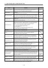
Gain switching function
You can switch gains during rotation and during stop, and can use an input device to
switch gains during operation.
Section 7.2
Advanced vibration
suppression control II
This function suppresses vibration at the arm end or residual vibration. Section 7.1.5
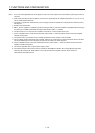
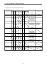
Machine resonance
suppression filter
This is a filter function (notch filter) which decreases the gain of the specific frequency
to suppress the resonance of the mechanical system.
Section 7.1.1
Shaft resonance suppression
filter
When a load is mounted to the servo motor shaft, resonance by shaft torsion during
driving may generate a mechanical vibration at high frequency. The shaft resonance
suppression filter suppresses the vibration.
Section 7.1.3
Adaptive filter II
Servo amplifier detects mechanical resonance and sets filter characteristics
automatically to suppress mechanical vibration.
Section 7.1.2
Low-pass filter
Suppresses high-frequency resonance which occurs as servo system response is
increased.
Section 7.1.4
Machine analyzer function
Analyzes the frequency characteristic of the mechanical system by simply connecting
a MR Configurator2 installed personal computer and servo amplifier.
MR Configurator2 is necessary for this function.
Robust filter
This function provides better disturbance response in case low response level that
load to motor inertia ratio is high for such as roll send axes.
[Pr. PE41]
Slight vibration suppression
control
Suppresses vibration of ±1 pulse produced at a servo motor stop. [Pr. PB24]
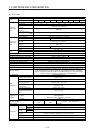
Auto tuning
Automatically adjusts the gain to optimum value if load applied to the servo motor
shaft varies.
Section 6.3
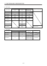
Brake unit
Used when the regenerative option cannot provide enough regenerative power.
Can be used for the 5 kW or more servo amplifier.
Section 11.3
Power regeneration converter
Used when the regenerative option cannot provide enough regenerative power.
Can be used for the 5 kW or more servo amplifier.
Section 11.4
Regenerative option
Used when the built-in regenerative resistor of the servo amplifier does not have
sufficient regenerative capability for the regenerative power generated.
Section 11.2
Alarm history clear Alarm history is cleared. [Pr. PC21]
Output signal selection
(device settings)
The output devices including ALM (Malfunction) and DB (Dynamic brake interlock) can
be assigned to certain pins of the CN3 connector.
[Pr. PD07] to
[Pr. PD09]
Output signal (DO) forced
output
Output signal can be forced on/off independently of the servo status.
Use this function for checking output signal wiring, etc.
Section 4.5.1
(1) (d)
Test operation mode
Jog operation, positioning operation, motor-less operation, DO forced output, and
program operation
MR Configurator2 is necessary for this function.
Section 4.5
Analog monitor output Servo status is output in terms of voltage in real time.
[Pr. PC09],
[Pr. PC10]
MR Configurator2
Using a personal computer, you can perform the parameter setting, test operation,
monitoring, and others.
Section 11.7
Linear servo system Linear servo system can be configured using a linear servo motor and liner encoder. Chapter 14
Direct drive servo system Direct drive servo system can be configured to drive a direct drive motor. Chapter 15