


14. USING A LINEAR SERVO MOTOR
14 - 5
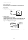
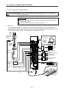
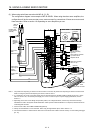
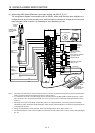
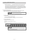
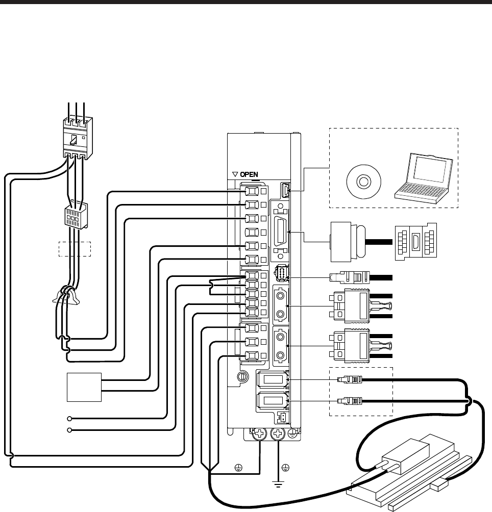
(3) When using A/B/Z-phase differential output linear encoder with MR-J4-_B_-RJ
The configuration diagram is an example of MR-J4-20B-RJ. When using the other servo amplifiers, the
configuration will be the same as rotary servo motors except for connections of linear servo motors and
linear encoders. Refer to section 1.8 depending on servo amplifiers you use.
CN5
P+
C
L11
L21
P3
P4
MR Configurator2
CN3
CN8
CN1A
CN1B
CN2
W
V
U
L1
L2
L3
RST
CN2L
Line noise
filter
(FR-BSF01)
Regenerative
option
Personal
computer
(Note 3)
Magnetic
contactor
(MC)
(Note 1)
Power factor
improving DC
reactor
(FR-HEL)
Molded-case
circuit breaker
(MCCB)
Junction
terminal
block
Safety relay or
MR-J3-D05 safety
logic unit
Servo system controller
or previous servo
amplifier CN1B
Next servo amplifier
CN1A or cap
(Note 2)
Power
supply
A/B/Z-phase
differential output
linear encoder
Linear servo motor
Encoder
cable
D
(Note 4)
Thermistor
(Note 5)
Note 1. The power factor improving AC reactor can also be used. In this case, the power factor improving DC reactor cannot be used.
When not using the power factor improving DC reactor, short P3 and P4.
2.
A
1-phase 200 V AC to 240 V AC power supply may be used with the servo amplifier of MR-J4-70B-RJ or less. For 1-phase
200 V AC to 240 V AC, connect the power supply to L1 and L3. Leave L2 open. For the power supply specifications, refer to
section 1.3.
3. Depending on the main circuit voltage and operation pattern, bus voltage decreases, and that may cause the forced stop
deceleration to shift to the dynamic brake deceleration. When dynamic brake deceleration is not required, slow the time to turn
off the magnetic contactor.
4.
A
lways connect between P+ and D terminals. When using the regenerative option, refer to section 11.2.
5. Connect the thermistor to CN2 of servo amplifier and connect the encoder cable to CN2L correctly. Incorrect setting will trigger
[AL. 16].