


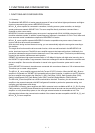
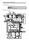
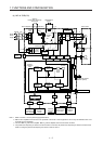
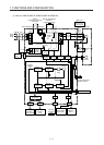
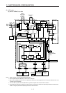
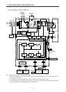
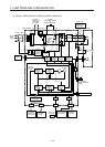

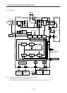
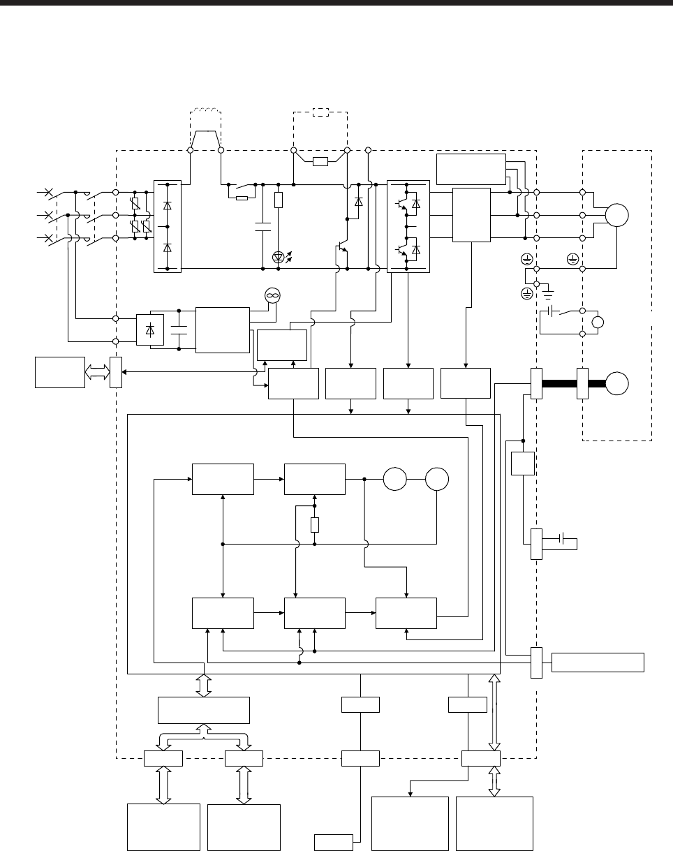
1. FUNCTIONS AND CONFIGURATION
1 - 5
(b) MR-J4-700B(-RJ)
L11
L21
Cooling fan
N-C
Power factor improving
DC reactor
(Note 1)
Power
supply
MCMCCB
STO
circuit
CN5
USB
USB
CN1A CN1B
D/A
CN3
Servo amplifier
U
V
W
U
V
W
P3 P4
Relay
(Note 2)
P+
+
+
B
RA
B1
B2
CN4
M
CN2
CN8
Control
circuit
power
supply
CHARGE
lamp
Regene-
rative
TR
Regenerative
option
L3
L2
L1
U U
U
Current
detection
Overcurrent
protection
Voltage
detection
Base
amplifier
STO
switch
Current
encoder
Dynamic
brake
circuit
Servo motor
Electromagnetic
brake
24 V DC
Encoder
Model position
Current
control
Actual
position
control
Actual
speed
control
Virtual
motor
Virtual
encoder
Position
command
input
Model speed Model torque
Model
position
control
Model
speed
control
Step-
down
circuit
Battery
(for absolute position
detection system)
I/F Control
Personal
computer
Servo system
controller or
servo amplifier
Servo
amplifier
or cap
Analog monitor
(2 channels)
Digital I/O
control
(Note 3)
(Note 4)
Diode
stack
CN2L
External encoder
Note 1. Refer to section 1.3 for the power supply specifications.
2. MR-J4 servo amplifier has P3 and P4 in the upstream of the inrush current suppression circuit. They are different from P1 and
P2 of MR-J3 servo amplifiers.
3. This is for MR-J4-_B-RJ servo amplifier. MR-J4-_B servo amplifier does not have CN2L connector.
4. The power factor improving AC reactor can also be used. In this case, the power factor improving DC reactor cannot be used.
When not using the power factor improving DC reactor, short P3 and P4.