


13. USING STO FUNCTION
13 - 6
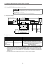
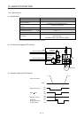
13.3 Connection example
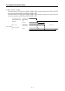
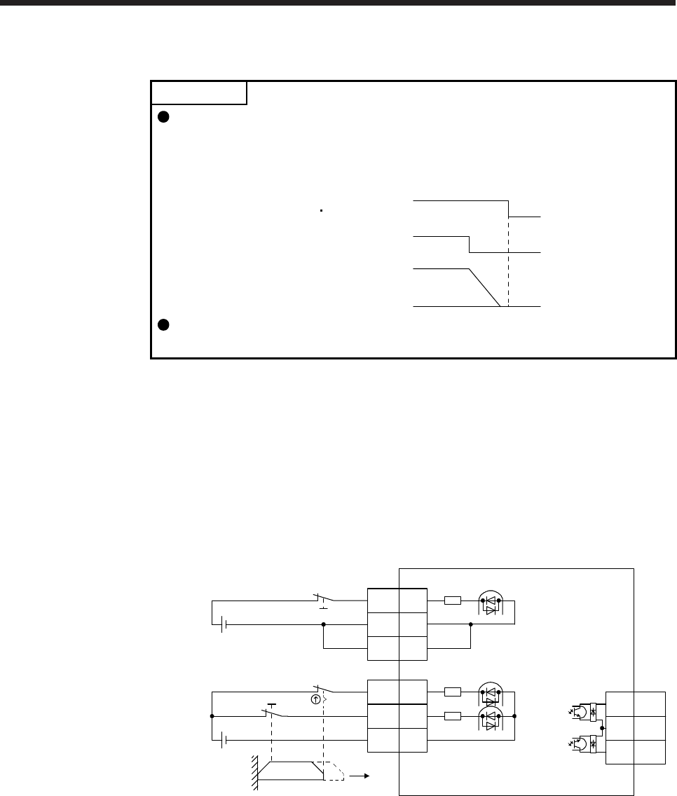
POINT
Turn off STO (STO1 and STO2) after the servo motor stops by the servo off
state or with forced stop deceleration by turning off EM2 (Forced stop 2).
Configure an external sequence that has the timings shown as below using an
external device such as the MR-J3-D05 safety logic unit.
STO2STO1
ON
OFF
ON
OFF
EM2
0 r/min
Servo motor
speed
If STO is turned off during operation, the servo motor is in dynamic brake stop
(stop category 0), and [AL.63 STO timing error] will occur.
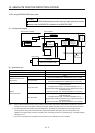
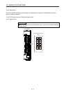
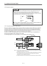
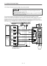
13.3.1 Connection example for CN8 connector
This servo amplifier is equipped with the connector (CN8) in accordance with the STO function. When this
connector is used with a certified external safety relay, power to the motor can be safely removed and
unexpected restart can be prevented. The safety relay used should meet the applicable safety standards
and have forcibly guided or mirror contacts for the purpose of error detection.
In addition, the MR-J3-D05 safety logic unit can be used instead of a safety relay for implementation of
various safety standards. Refer to Appendix 5 for details.
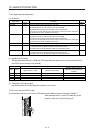
The following diagram is for source interface. For sink interface, refer to section 13.4.1.
Approx.
3.0 kΩ
24 V DC
24 V DC
STO1
STO2
Door
Open
(Note 2)
(Note 2)
(Note 3)
CN8 (Note 1)
STO1
CN8
Forced stop 2
4
STO2
5
STOCOM
3
Approx.
3.0 kΩ
Servo amplifier
EM2
CN3
20
DICOM
5
DICOM
10
Approx.
6.2 kΩ
8
6
TOFCOM
7
TOFB2
TOFB1
Note 1. By using TOFB, whether the servo is in the STO state can be confirmed. For connection
examples, refer to section 13.3.2 to 13.3.4.
2. When using the STO function, turn off STO1 and STO2 at the same time. Turn off STO1
and STO2 after the servo motor stops by the servo off state or with forced stop
deceleration by turning off EM2 (Forced stop 2).
3. Configure the interlock circuit so that the door is open after the servo motor is stopped.