


3. SIGNALS AND WIRING
3 - 18
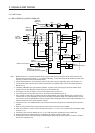
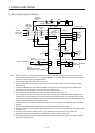
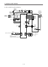
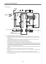
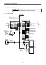
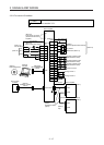
3.3 Explanation of power supply system
3.3.1 Signal explanations
POINT
For the layout of connector and terminal block, refer to chapter 9 DIMENSIONS.
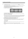
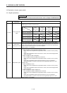
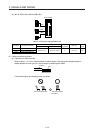
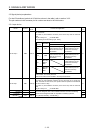
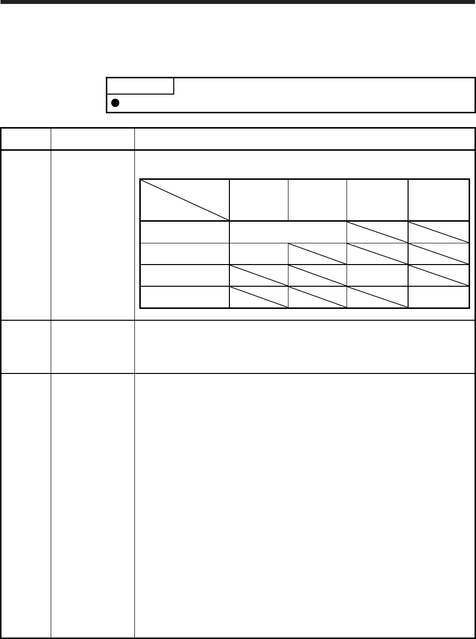
Symbol
Connection target
(application)
Description
L1/L2/L3
Main circuit power
supply
Supply the following power to L1, L2, and L3. For 1-phase 200 V AC to 240 V AC, connect the
power supply to L1 and L3. Leave L2 open.
Servo amplifier
Power
MR-J4-10B
(-RJ) to
MR-J4-70B
(-RJ)
MR-J4-100B
(-RJ) to
MR-J4-22KB
(-RJ)
MR-J4-60B4
(-RJ) to
MR-J4-22KB4
(-RJ)
MR-J4-10B1 to
MR-J4-40B1
3-phase 200 V AC to
240 V AC, 50 Hz/60 Hz
L1/L2/L3
1-phase 200 V AC to
240 V AC, 50 Hz/60 Hz
L1/L3
3-phase 380 V AC to
480 V AC, 50 Hz/60 Hz
L1/L2/L3
1-phase 100 V AC to
120 V AC, 50 Hz/60 Hz
L1/L2
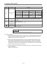
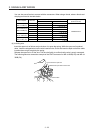
P3/P4
Power factor
improving DC reactor
When not using the power factor improving DC reactor, connect P3 and P4. (factory-wired)
When using the power factor improving DC reactor, disconnect P3 and P4, and connect the
power factor improving DC reactor to P3 and P4. Additionally, the power factor improving DC
reactor cannot be used for the 100 V class servo amplifiers.
Refer to section 11.11 for details.
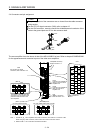
P+/C/D Regenerative option
(1) 200 V class/100 V class
1) MR-J4-500B(-RJ) or less and MR-J4-40B1(-RJ) or less
When using a servo amplifier built-in regenerative resistor, connect P+ and D. (factory-
wired)
When using a regenerative option, disconnect P+ and D, and connect the regenerative
option to P+ and C.
2) MR-J4-700B(-RJ) to MR-J4-22KB(-RJ)
MR-J4-700B(-RJ) to MR-J4-22KB(-RJ) do not have D.
When using a servo amplifier built-in regenerative resistor, connect P+ and C. (factory-
wired)
When using a regenerative option, disconnect wires of P+ and C for the built-in
regenerative resistor. And then connect wires of the regenerative option to P+ and C.
(2) 400 V class
1) MR-J4-350B4(-RJ) or less
When using a servo amplifier built-in regenerative resistor, connect P+ and D. (factory-
wired)
When using a regenerative option, disconnect P+ and D, and connect the regenerative
option to P+ and C.
2) MR-J4-500B4(-RJ) to MR-J4-22KB4(-RJ)
MR-J4-500B4(-RJ) to MR-J4-22KB4(-RJ) do not have D.
When using a servo amplifier built-in regenerative resistor, connect P+ and C. (factory-
wired)
When using a regenerative option, disconnect wires of P+ and C for the built-in
regenerative resistor. And then connect wires of the regenerative option to P+ and C.
Refer to section 11.2 for details.