


11. OPTIONS AND PERIPHERAL EQUIPMENT
11 - 41
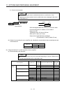
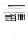
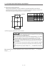
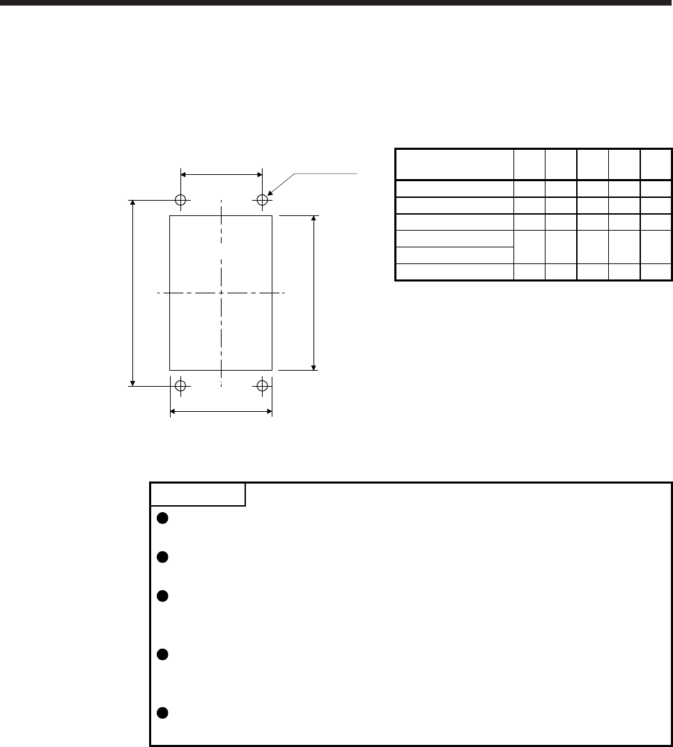
(4) Mounting hole machining dimensions
When the power regeneration converter is installed to an enclosed type cabinet, mount the heat
generating area of the converter outside the box to provide heat generation measures. At this time, the
mounting hole having the following dimensions is machined in the box.
[Unit: mm]
(AA)
(BA)
b
a
(2-φD hole)
(Mounting hole)
Power regeneration
converter
a b D AA BA
FR-RC-15K 260 412 10 200 432
FR-RC-30K 330 562 10 270 582
FR-RC-55K 470 642 12 410 670
FR-RC-H15K
330 562 10 270 582
FR-RC-H30K
FR-RC-H55K 470 642 12 410 670
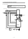
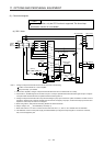
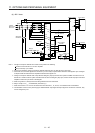
11.5 FR-CV-(H) power regeneration common converter
POINT
For details of the power regeneration common converter FR-CV-(H), refer to the
FR-CV Installation Guide (IB(NA)0600075).
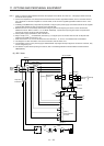
Do not supply power to the main circuit power supply terminals (L1, L2, and L3)
of the servo amplifier. Doing so will fail the servo amplifier and FR-CV-(H).
Connect the DC power supply between the FR-CV-(H) and servo amplifier with
correct polarity. Connection with incorrect polarity will fail the FR-CV-(H) and
servo amplifier.
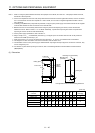
Two or more FR-CV-(H)s cannot be installed to improve regeneration capability.
Two or more FR-CV-(H)s cannot be connected to the same DC power supply
line.
When using FR-CV-(H), set [Pr. PA04] to "0 0 _ _" to enable EM1 (Forced stop
1).
When using the FR-CV-(H) power regeneration common converter, set [Pr. PA02] to "_ _ 0 1" and set [Pr.
PC20] to "_ _ _ 1".