7. SPECIAL ADJUSTMENT FUNCTIONS
7 - 22
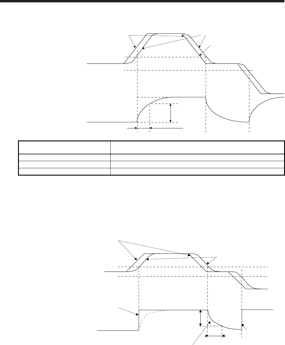
(b) Switching timing chart
After-switching gain
63.4%
CDT = 100 ms
Before-switching gain
Gain switching
Droop pulses
[pulse]
+CDL
-CDL
0
Command pulses
Droop pulses
Command pulses
Load to motor inertia ratio/load to motor
mass ratio
4.00 → 10.00 → 4.00 → 10.00
Position loop gain 120 → 84 → 120 → 84
Speed loop gain 3000 → 4000 → 3000 → 4000
Speed integral compensation 20 → 50 → 20 → 50
(3) When the gain switching time constant is disabled
(a) Gain switching time constant disabled was selected.
The gain switching time constant is disabled with this setting. The time constant is enabled at gain
return.
The following example shows for [Pr. PB26 (CDP)] = 0103, [Pr. PB27 (CDL)] = 100 [pulse], and [Pr.
PB28 (CDT)] = 100 [ms].
Command pulses
Droop pulses
+100 pulses
-100 pulses
0Droop pulses [pulse]
Switching time constant
disabled
Switching at 0 ms
After-switching gain
Before-switching gain
Switching at [Pr. PB28 (CDT)] = 100 [ms] only when gain switching off (when returning)
CDT = 100 ms
63.4%
Switching at 0 ms
After-switching gain
Gain switching


