


11. OPTIONS AND PERIPHERAL EQUIPMENT
11 - 44
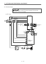
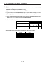
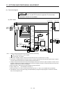
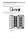
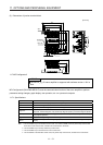
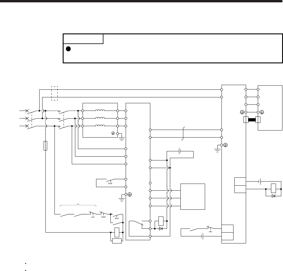
(3) Connection diagram
POINT
In this configuration, only the STO function is supported. The forced stop
deceleration function is not available.
(a) 200 V class
MCMCCB
R/L11
S/L21
T/L31
S2/L22
R2/L12
T2/L32
FR-CVL
MC
RA2RA1
EM1
RESET
MC
SK
RA1
EM1
R2/L1
S2/L2
N/L-
P24
SD
RDYB
RDYA
RSO
SE
SD
P/L+
T2/L3
R/L11
S/L21
T/MC1
RES
L11
L21
P4
N-
U
V
W
EM1
U
V
W
CN2
FR-CV
DICOM
B
C
A
RA1
DOCOM
ALM
RA2
3-phase
200 to
230 V AC
OFF
ON
(Note 1)
(Note 1)
Servo motorServo amplifier
Servo system
controller
(Note 5)
(Note 7)
24 V DC (Note 8)
24 V DC (Note 8)
(Note 4)
(Note 1, 6)
(Note 2)
(Note 3)
24 V DC (Note 8)
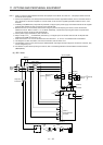
Note 1. Configure a sequence that will shut off main circuit power in the following.
An alarm occurred at FR-CV or servo amplifier.
EM1 (Forced stop 1) is enabled.
2. For the servo amplifier, configure a sequence that will switch the servo-on after the FR-CV is ready.
3. For the FR-CV, the RSO signal turns off when it is put in a ready-to-operate status where the reset signal is input. Configure
a sequence that will make the servo inoperative when the RSO signal is on.
4. Configure a sequence that will make a stop with the emergency stop input of the servo system controller if an alarm occurs in
the FR-CV. When the servo system controller does not have an emergency stop input, use the forced stop input of the servo
amplifier to make a stop as shown in the diagram.
5. When using FR-CV, always disconnect wiring between P3 and P4 terminals.
6. Set [Pr. PA04] to "0 0 _ _" to enable EM1 (Forced stop 1).
7. When wires used for L11 and L21 are thinner than wires used for L1, L2, and L3, use a molded-case circuit breaker.
8. The illustration of the 24 V DC power supply is divided between input signal and output signal for convenience. However,
they can be configured by one.