


3. SIGNALS AND WIRING
3 - 16
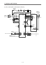
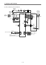
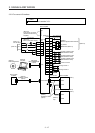
Note 1. To prevent an electric shock, always connect the protective earth (PE) terminal (marked ) of the servo amplifier to the
protective earth (PE) of the cabinet.
2. Connect the diode in the correct direction. If it is connected reversely, the servo amplifier will malfunction and will not output
signals, disabling EM2 (Forced stop 2) and other protective circuits.
3. If the controller does not have forced stop function, always install the forced stop 2 switch (normally closed contact).
4. When starting operation, always turn on EM2 (Forced stop 2). (Normally closed contact)
5. Use SW1DNC-MRC2-E. (Refer to section 11.7.)
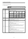
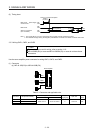
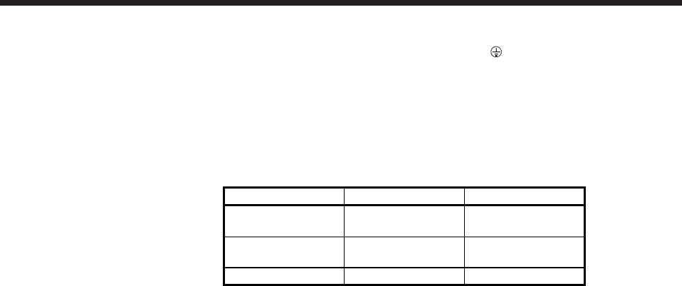
6. Use SSCNET III cables listed in the following table.
Cable Cable model Cable length
Standard cord inside
cabinet
MR-J3BUS_M 0.15 m to 3 m
Standard cable
outside cabinet
MR-J3BUS_M-A 5 m to 20 m
Long-distance cable MR-J3BUS_M-B 30 m to 50 m
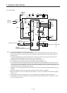
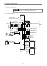
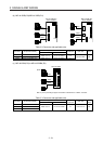
7. The wiring after the second servo amplifier is omitted.
8. Up to 64 axes of servo amplifiers can be connected. The number of connectable axes depends on the controller you use.
Refer to section 4.3.1 for setting of axis selection.
9. Make sure to cap the unused CN1B connector.
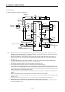
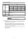
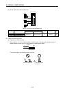
10. Supply 24 V DC ± 10% for interfaces from outside. Set the total current capacity to 300 mA. 300 mA is the value applicable
when all I/O signals are used. The current capacity can be decreased by reducing the number of I/O points. Refer to section
3.8.2 (1) that gives the current value necessary for the interface. The illustration of the 24 V DC power supply is divided
between input signal and output signal for convenience. However, they can be configured by one.
11.
A
LM (Malfunction) turns on in normal alarm-free condition. (Normally closed contact)
12. The pins with the same signal name are connected in the servo amplifier.
13. You can change devices of these pins with [Pr. PD07], [Pr. PD08], and [Pr. PD09].
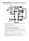
14. Devices can be assigned for these signals with controller setting. For devices that can be assigned, refer to the controller
instruction manual. The following devices can be assigned for R_MTCPU, Q17_DSCPU, RD77MS_ and QD77MS_.
FLS: Upper stroke limit
RLS: Lower stroke limit
DOG: Proximity dog
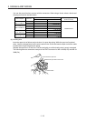
15. Configure a circuit to turn off EM2 when the main circuit power is turned off to prevent an unexpected restart of the servo
amplifier.
16. When not using the STO function, attach the short-circuit connector came with a servo amplifier.
17. When you use a linear servo motor or direct drive motor, use MBR (Electromagnetic brake interlock) for an external brake
mechanism.