


11. OPTIONS AND PERIPHERAL EQUIPMENT
11 - 26
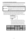
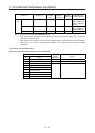
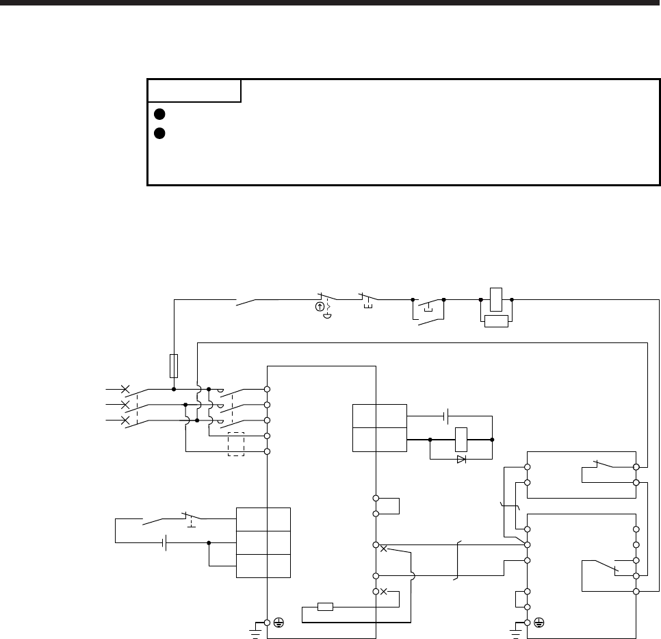
11.3.3 Connection example
POINT
EM2 has the same function as EM1 in the torque control mode.
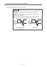
Connecting PR terminal of the brake unit to P+ terminal of the servo amplifier
results in brake unit malfunction. Always connect the PR terminal of the brake
unit to the PR terminal of the resistor unit.
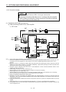
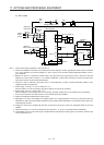
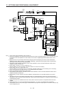
(1) Combination with FR-BR-(H) resistor unit
(a) When connecting a brake unit to a servo amplifier
1) 200 V class
Emergency stop switch
3
DOCOM
ALM
Servo amplifier
15
CN3
(Note 9)
MC
MCCB
(Note 1)
Power
supply
L1
L2
L3
L11
L21
ALM
RA1
OFF
MC
ON
MC
SK
P3
P4
(Note 3)
P+
N-
C
(Note 2)
(Note 7)
(Note 11)
N/-
P/+
BUE
SD
PR
B
C
A
SD
MSG
(Note 4)
(Note 6)
FR-BU2
FR-BR
P
PR
TH2
TH1
(Note 5)
(Note 8)
RA1
CN3
(Note 10)
Main circuit
power supply
24 V DC (Note 12)
5
10
EM2
DICOM
DICOM
20
24 V DC (Note 12)
Note 1. For the power supply specifications, refer to section 1.3.
2. For the servo amplifier of 7 kW, always disconnect the lead wire of built-in regenerative resistor, which is connected to P+ and
C terminals. For the servo amplifier of 11 kW to 22 kW, do not connect a supplied regenerative resistor to the P+ and C
terminals.
3. Between P3 and P4 is connected by default. When using the power factor improving DC reactor, remove the short ba
r
between P3 and P4. Refer to section 11.11 for details. Additionally, a power factor improving DC reactor and power facto
r
improving AC reactor cannot be used simultaneously.
4. Connect P/+ and N/- terminals of the brake unit to a correct destination. Incorrect connection destination results in servo
amplifier and brake unit malfunction.
5. Contact rating: 1b contact, 110 V AC, 5 A/220 V AC, 3 A
Normal condition: TH1-TH2 is conducting. Abnormal condition: TH1-TH2 is not conducting.
6. Contact rating: 230 V AC, 0.3 A/30 V DC, 0.3 A
Normal condition: B-C is conducting./A-C is not conducting. Abnormal condition: B-C is not conducting./A-C is conducting.
7. Do not connect more than one cable to each P+ to N- terminals of the servo amplifier.
8.
A
lways connect BUE and SD terminals. (factor
y
-wired)
9. Depending on the main circuit voltage and operation pattern, bus voltage decreases, and that may cause the forced stop
deceleration to shift to the dynamic brake deceleration. When dynamic brake deceleration is not required, slow the time to turn
off the magnetic contactor.
10. Configure a circuit to turn off EM2 when the main circuit power is turned off to prevent an unexpected restart of the servo
amplifier.
11. When wires used for L11 and L21 are thinner than wires used for L1, L2, and L3, use a molded-case circuit breaker.
12. The illustration of the 24 V DC power supply is divided between input signal and output signal for convenience. However, the
y
can be configured by one.